Module 1 - Setup
For Digital Sistem Design (DSG) or Perancangan Sistem Digital (PSD) Practicum, students must have already installed between Vivado only or ModelSim + Quartus Prime
- Vivado Installation Tutorial
- Vivado Simulation and Synthesis Tutorial
- Quartus Prime Installation Tutorial
- Quartus Prime Synthesis Tutorial
- ModelSim Installation Tutorial
- ModelSim Simulation Tutorial
Vivado Installation Tutorial
1.1 Vivado Explanation
Vivado is an Integrated Design Environment (IDE) developed by Xilinx (now AMD) used for designing, simulating, and implementing digital circuits on FPGAs (Field-Programmable Gate Arrays). It serves as the primary software tool to take a VHDL hardware description and turn it into a functional circuit on a physical chip. Vivado itself is a complete, integrated workshop for Xilinx FPGAs. It has all the tools you need (design, simulation, implementation) under one roof.
Before choosing Vivado be cautious that Vivado requires atleast 60gb of storage and a demanding CPU performance.
1.2 Vivado Installation
To install Vivado, please follow this link and proceed to do the next procedure until finished.
Step 1 : Download the Vivado Installer
Go into Vivado Archive and choose version 2022.2.
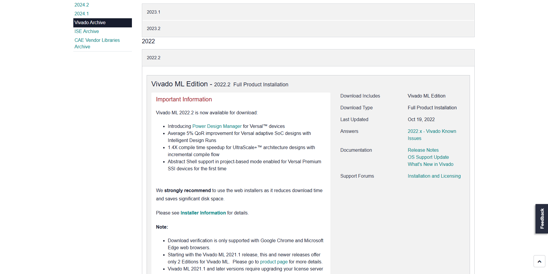
Then Scroll and choose Windows version and then click the link
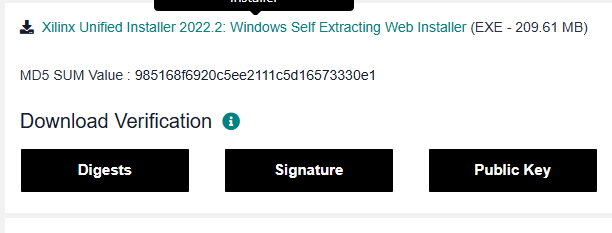
The link will take you into a login page, you may create a new account or if you already had one you can just log into your AMD account.

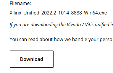
The page will take you into the download center where you will fill out your information, you may just fill up only the required part to download the installer. After filling all your information, you can just download the installer on the bottom of the page.
Step 2 : Install the Vivado
Run the installation file

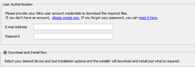
Proceed to log into the same account you've just logged into/created before in step 1 and then just choose Download and install now and proceed into the next step
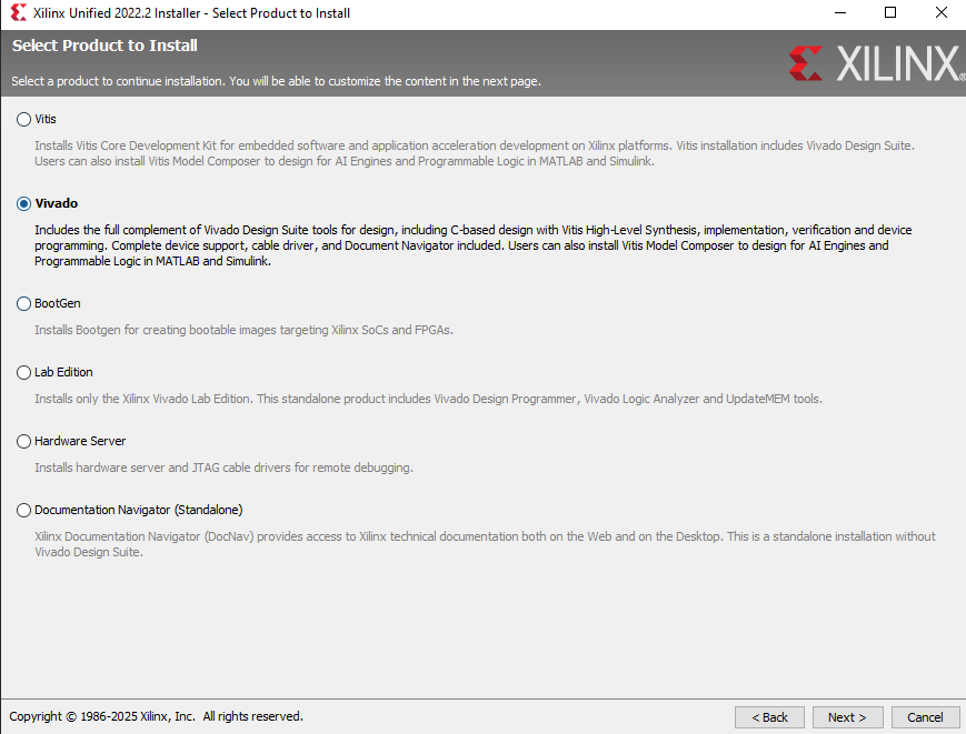
Choose Vivado and then proceed
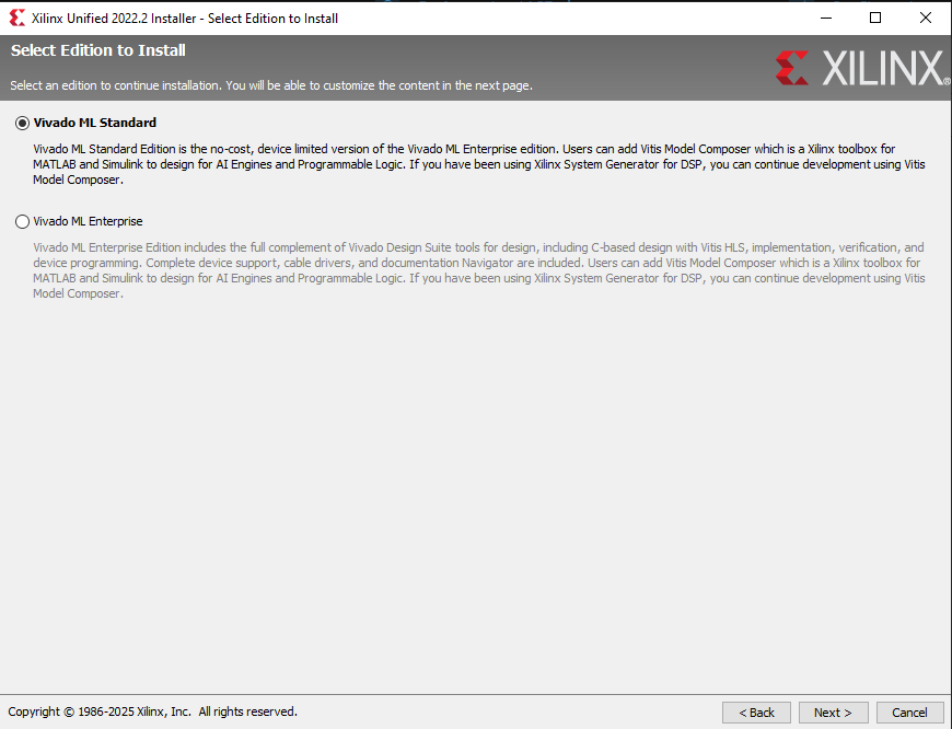
Choose Vivado ML Standard and proceed
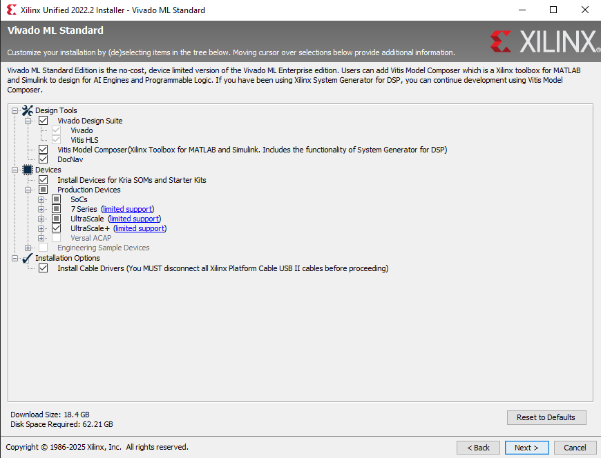
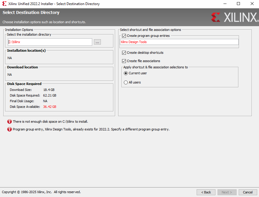
Just Check every box like in the screenshot below and make sure to have enough disk space required on the bottom left and then ou may proceed.
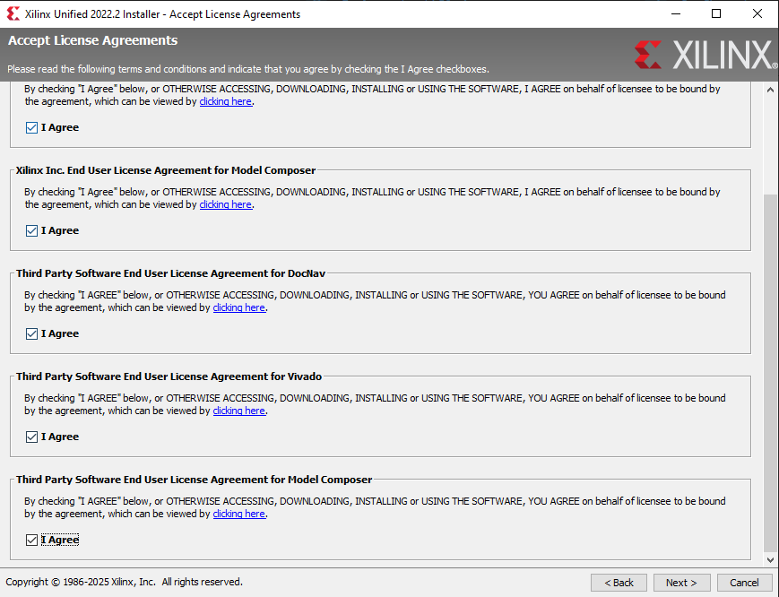
Just check all the agree box and you may proceed
Choose where you want Vivado to be installed and then you may proceed to the installation part
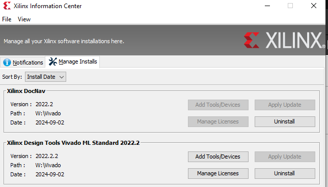
Wait until the installation is completed and then you may check in xilinx information center if the Vivado installation had completed. Make sure to check if the Version you've installed is correct.

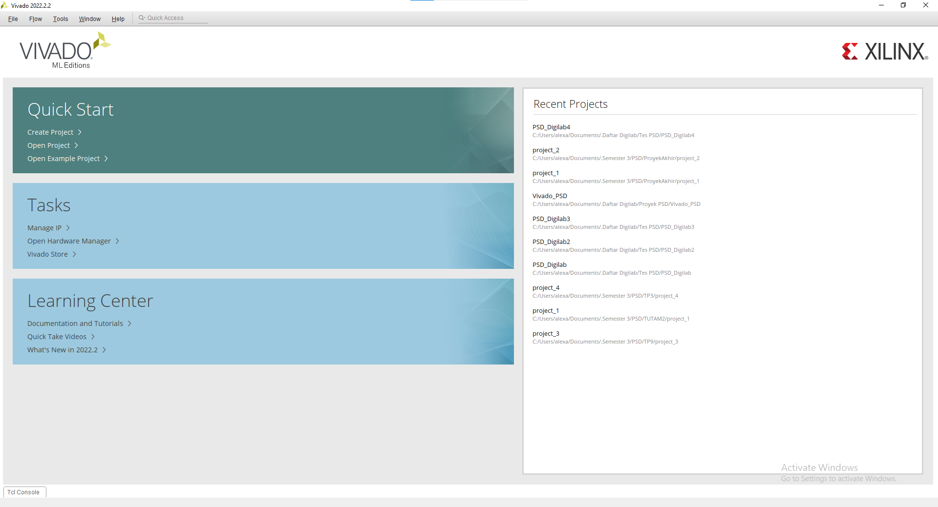
You may open Vivado and voila you've installed Vivado

Vivado Simulation and Synthesis Tutorial
1.3 Vivado Tutorial
For this tutorial, we will use this code for reference :
LIBRARY IEEE;
USE IEEE.STD_LOGIC_1164.ALL;

ENTITY AND_GATE IS
    PORT (
        A : IN  STD_LOGIC;
        B : IN  STD_LOGIC;
        Y : OUT STD_LOGIC
    );
END AND_GATE;

ARCHITECTURE Behavioral OF AND_GATE IS
BEGIN
    Y <= A AND B;
END Behavioral;
1.3.1 Creating a new Vivado file
Create a new project
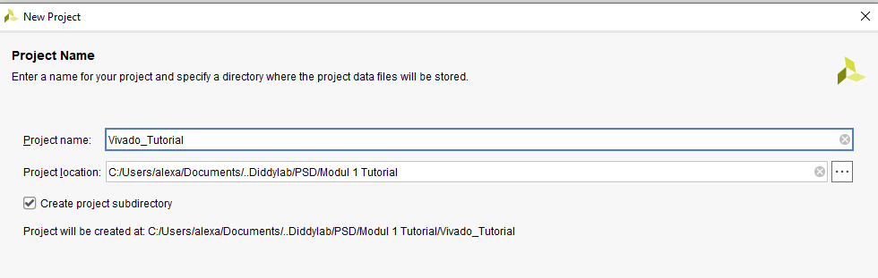
Enter your project name and where you want it to be saved
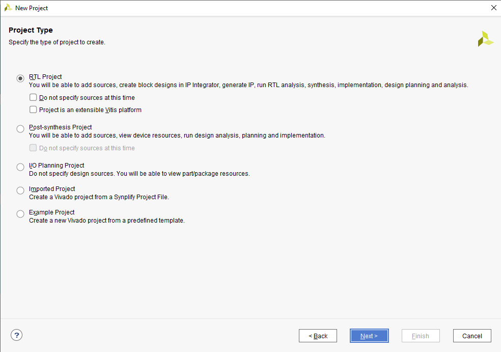
Choose RTL Project
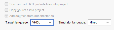
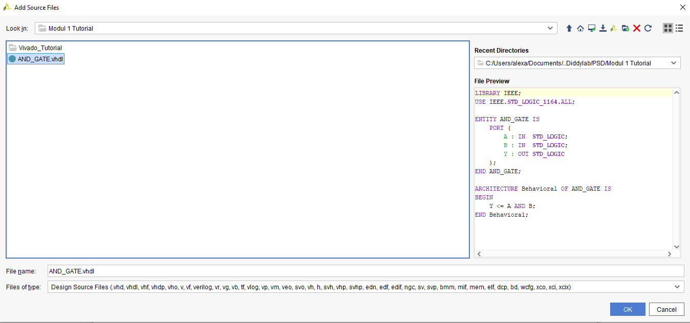
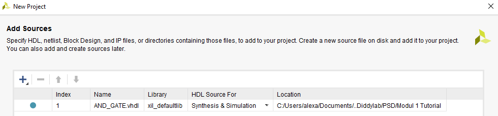
Change the target language into VHDL and add your VHDL code into the project
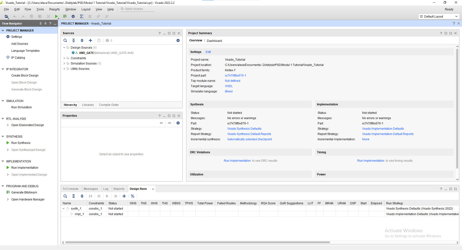
You may skip the add constraints page and also the default part proceed into the project creation. Finally you've created a new project and this will be your screen now.
1.3.2 Simulation Tutorial
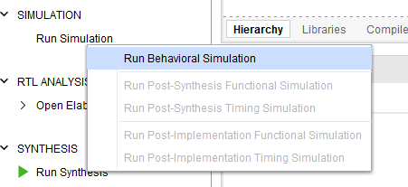
Click "Run Simulation" on the left part of the screen. And choose "Run Behavorial Simulation"
If there's any error warning, you may read and fix the error before proceeding into the simulation.
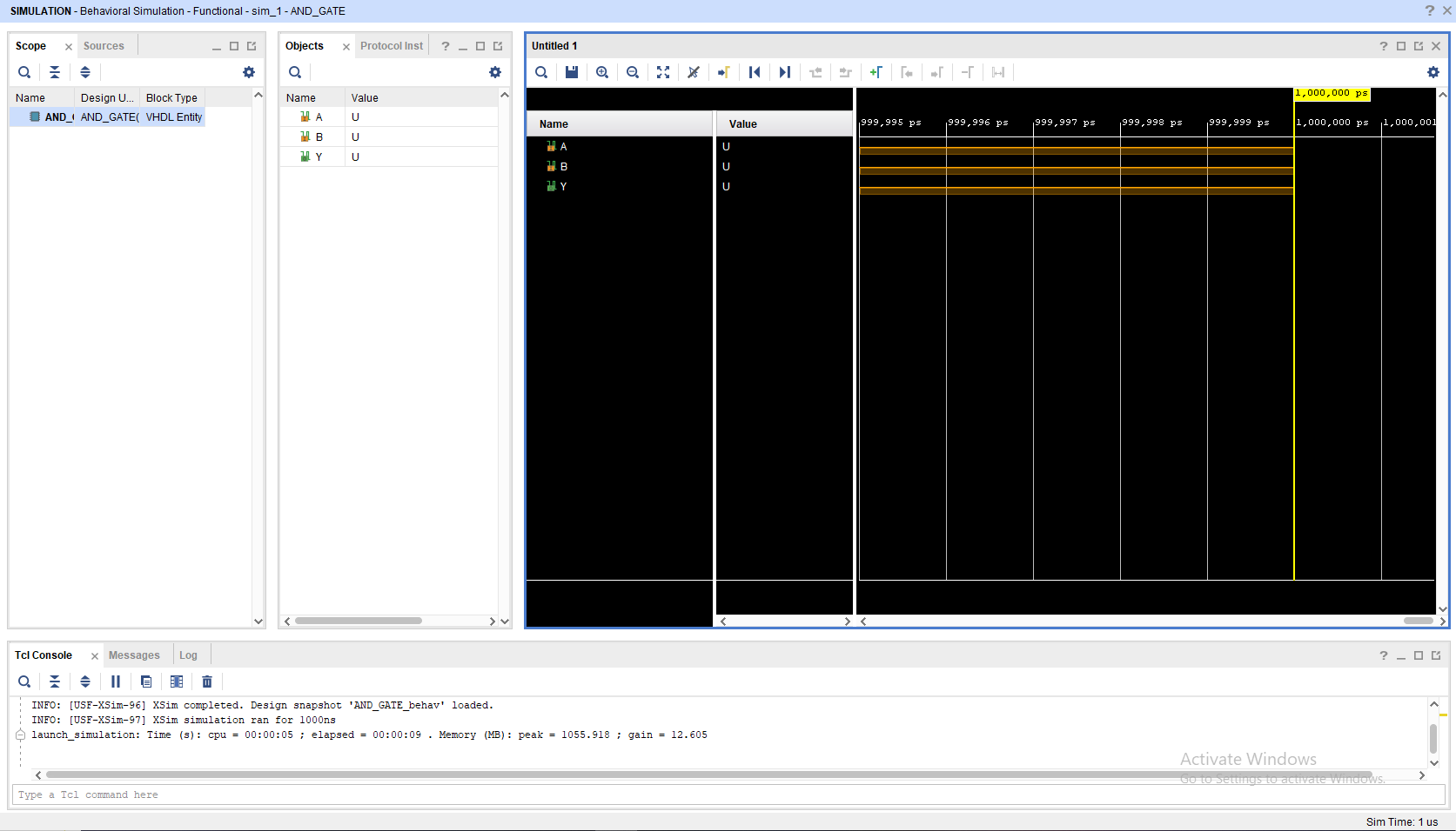
This will be your screen after you run the simulation.
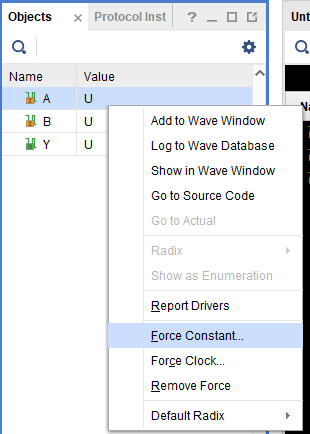
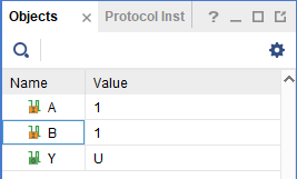
To add a signal, you may change the value in the objects part, choose "Force Constant" and change according to what you want to do. Remember to change the INPUT not the OUTPUT
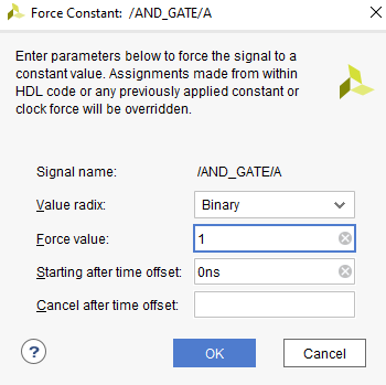
After changing the Value you may click the "Run for 10ns" on the top bar
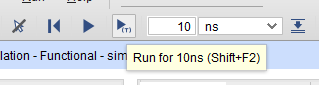
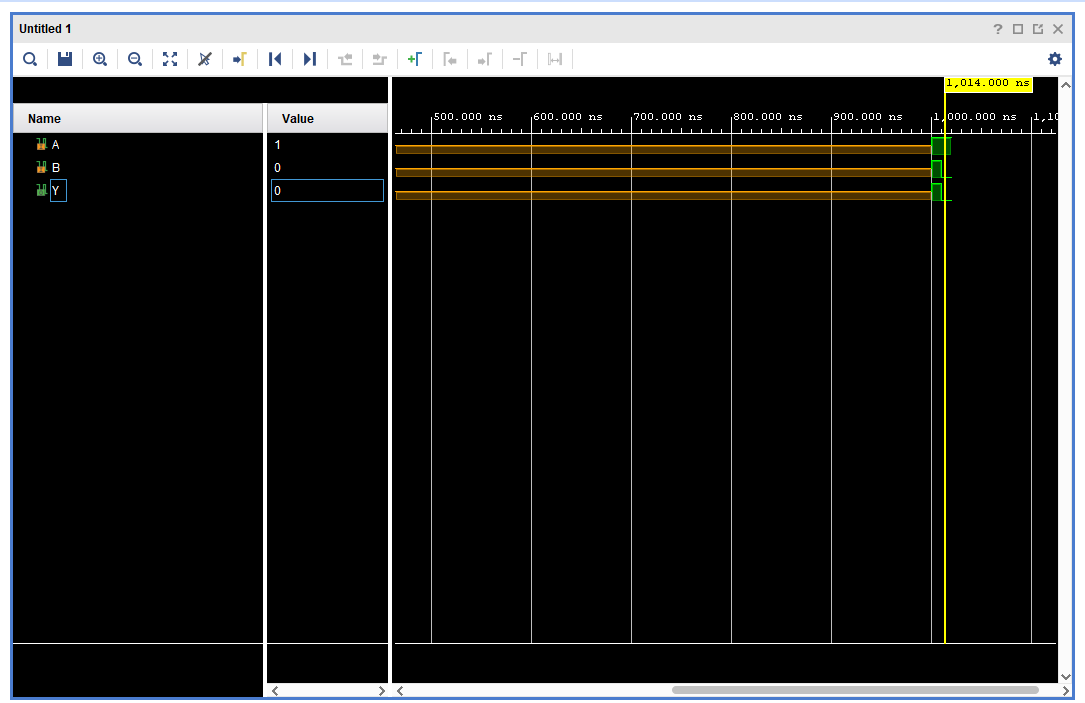
You may see that there's a new signal after you press the button
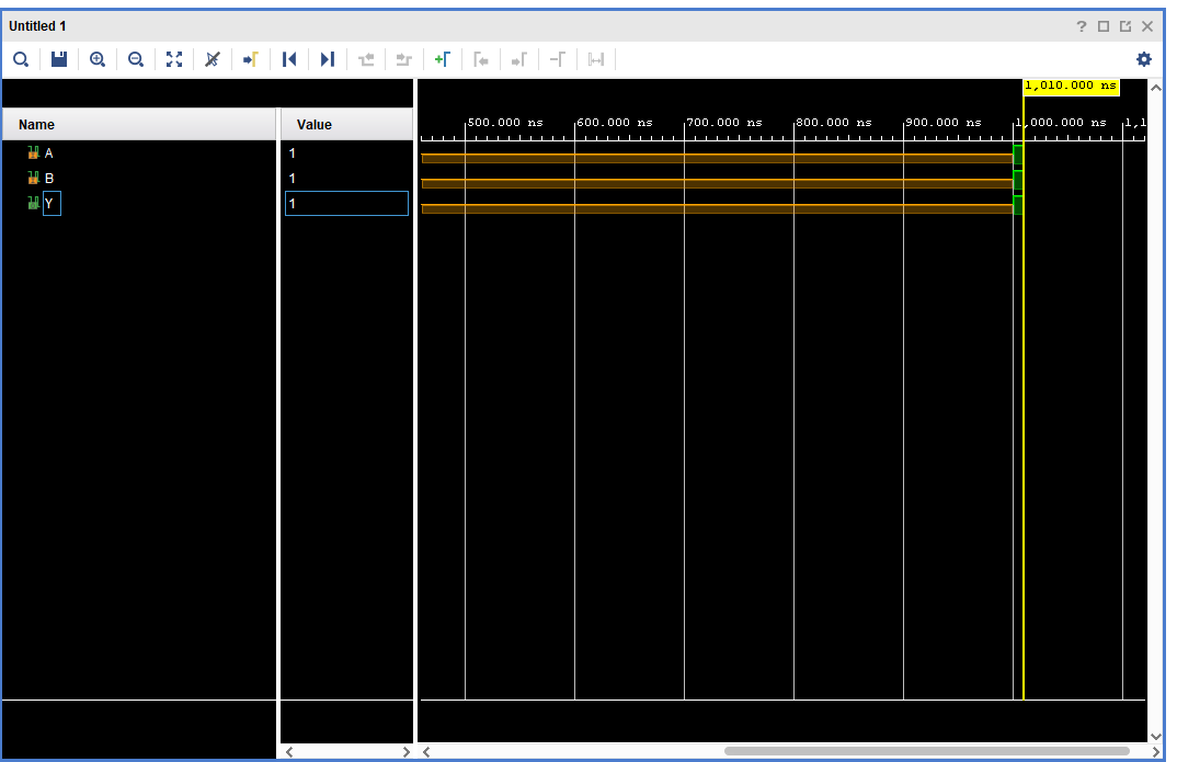
You may also move the yellow line with your cursor to switch to a different period of time on the waveform
NOTE : All of this is just a manual simulation tutorial. There are a way to do this automatically (Hint: Module 4).
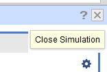
To close simulation, you may click the top right button
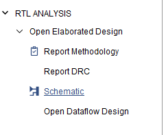
1.3.3 Synthesis Tutorial
Go to the "RTL Analysis" and run "Schematic" and if there's a notification just select "ok"
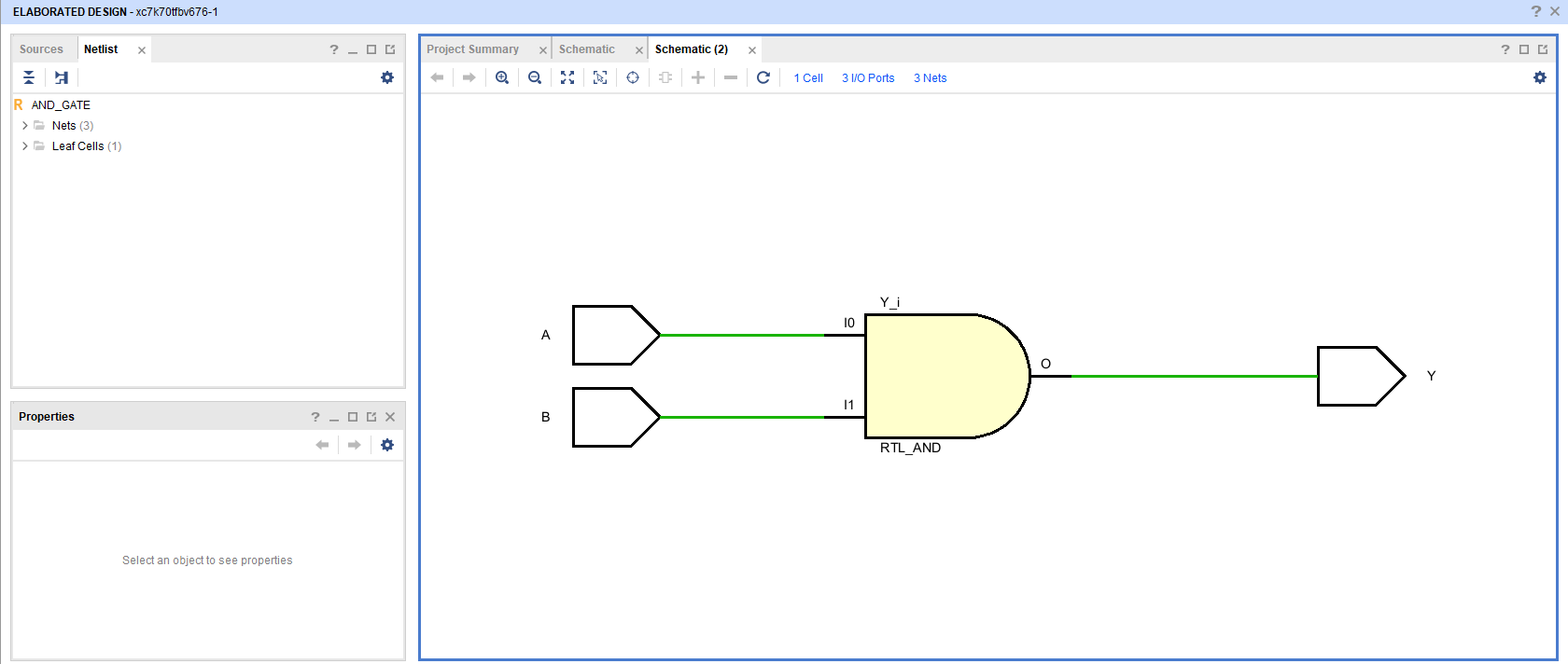
Wait until the elaborated design is finished and then you may see your VHDL code schematic.
Quartus Prime Installation Tutorial
1.1 Quartus Prime Explanation
Intel Quartus Prime is a comprehensive software suite from Intel used for designing, synthesizing, and programming programmable logic devices (PLDs), such as Field-Programmable Gate Arrays (FPGAs) and Complex Programmable Logic Devices (CPLDs). The software provides a complete integrated development environment (IDE) for digital circuit engineers and designers.
1.2 Quartus Prime Installation
To install Quartus Prime, please follow this link and proceed to do the next procedure until finished.
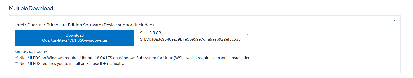
Step 1 : Download the Quartus Prime Installer
Go into Multiple Download and then download the Intel Quartus Prime installer :
The link will take you into an software license agreement, just accept the terms and proceed with the download.
Step 2 : Install the Quartus Prime
Extract the zip and then Run the installation file setup.

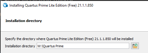
If the installer ask you to accept the agreement just accept and proceed with the next part. And then choose the directory for where you want the Quartus Prime to be installed.
NOTE : Do not use space in the folder naming.
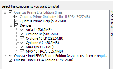
Check every components and proceed with the installation.
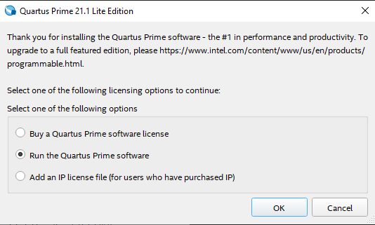
Wait until the installation is finished and then voila you've installed Quartus Prime. To run it just choose to run the Quartus Prime software.
Quartus Prime Synthesis Tutorial
1.3 Quartus Prime Tutorial
For this tutorial, we will use this code for reference :
LIBRARY IEEE;
USE IEEE.STD_LOGIC_1164.ALL;

ENTITY AND_GATE IS
    PORT (
        A : IN  STD_LOGIC;
        B : IN  STD_LOGIC;
        Y : OUT STD_LOGIC
    );
END AND_GATE;

ARCHITECTURE Behavioral OF AND_GATE IS
BEGIN
    Y <= A AND B;
END Behavioral;
1.3.1 Creating a New Quartus Prime Project
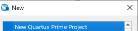
Create a new project by clicking new on file tab
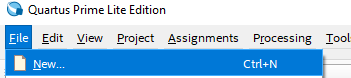
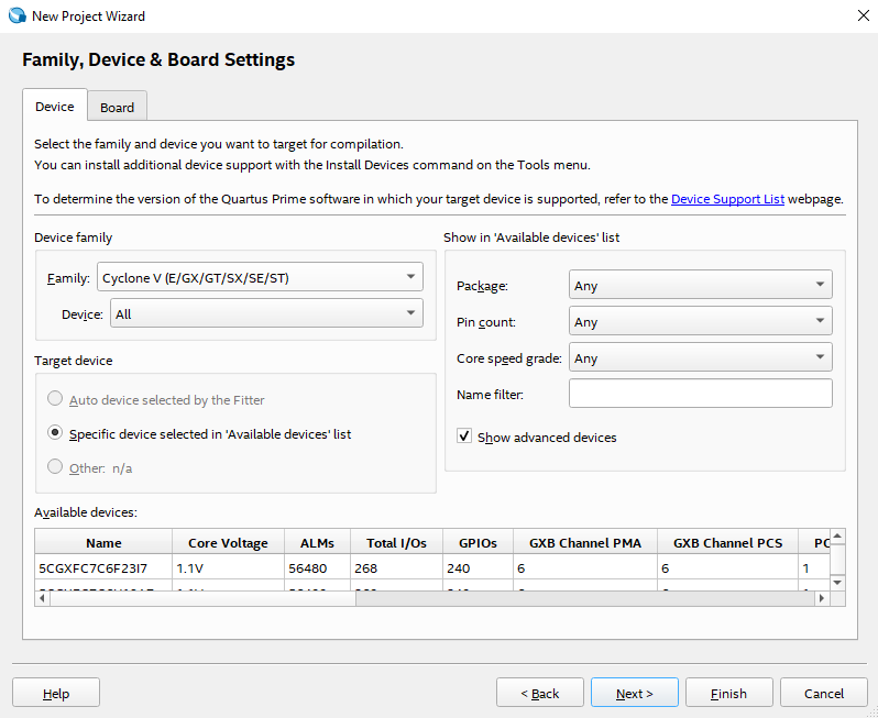
Select New Quartus Prime Project
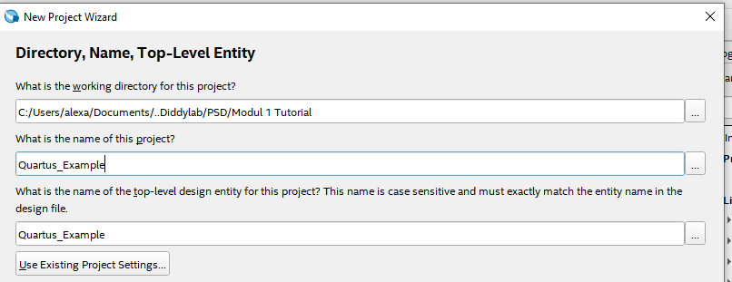
Select the directory where you want the project to be saved and also give the project a name and name your Top-Level Entity
NOTE : Remember to name your Top-Level Entity into the same name as your Top-Level entity on your .vhdl
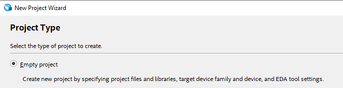
Choose empty project
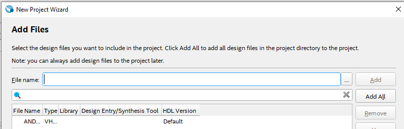
Add your .vhdl/.vhd file into the project
Just select the default setting and proceed to finish
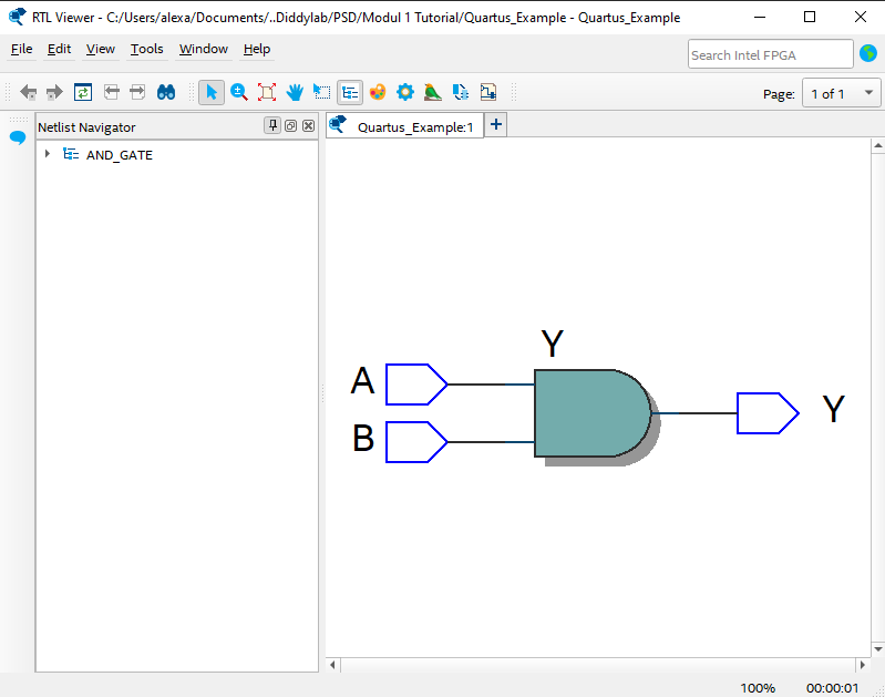
1.3.2 Synthesis Tutorial
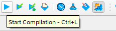
Run the "Start Compilation" button on top bar
Wait until the startup is finish and then go into Tools -> Netlist Viewers -> RTL Viewer
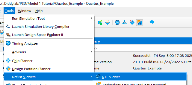
You may see your VHDL schematic