Module 4 - Testbench
- 1. Understanding Testbench in VHDL
- 2. Components of a Testbench
- 3. Testbench Architecture Models
- 4. Assert and Report Statement
- 5. File I/O in VHDL
- Extra: Array in VHDL
1. Understanding Testbench in VHDL
A VHDL testbench is a non-synthesizable VHDL entity used to simulate and verify the functionality of another VHDL entity, often referred to as the Unit Under Test (UUT). Think of it as a virtual lab environment where you can apply a sequence of inputs (stimulus) to your design and observe its behavior and outputs over time. Since the testbench itself is not meant to be turned into a physical chip, it can use more abstract and powerful VHDL constructs that are not available for synthesizable hardware descriptions.
A testbench has many uses, including:
- Simplifying and speeding up the entity testing process because inputs do not need to be manually entered one by one through a simulation tool.
- Allowing the entity's output to be compared against predetermined values to verify its correctness.
- Enabling the test results to be saved into files, such as a .csv file, so they can be used by other software like Python, Excel, or MATLAB for further analysis.
2. Components of a Testbench
2.1 Entity Declaration
The testbench entity is declared without any ports. It's a self-contained module because it doesn't connect to any higher-level design; it is the top-level entity for the simulation.
entity project_tb is
    -- Empty because testbench doesn't have any port
end project_tb
2.2 Architecture Declaration
2.2.1 UUT Component Declaration
Inside the architecture, we first declare the entity we want to test (the UUT) as a component. The component declaration must match the entity declaration of the UUT.
For example, if we have a UUT with these entity declaration:
entity earth_destroyer is
    Port (
        clk, rst    : IN STD_LOGIC;
        input       : IN STD_LOGIC VECTOR(7 downto 0);
        mode        : IN STD_LOGIC_VECTOR(3 downto 0);
        output      : OUT STD_LOGIC_VECTOR(7 downto 0)
    );
end earth_destroyer;
The UUT component declaration for that entity will be:
component earth_destroyer is
    Port (
        clk, rst    : IN STD_LOGIC;
        input       : IN STD_LOGIC VECTOR(7 downto 0);
        mode        : IN STD_LOGIC_VECTOR(3 downto 0);
        output      : OUT STD_LOGIC_VECTOR(7 downto 0)
    );
end component;
As you can see, component declaration is almost the exact same as entity declaration. Just make sure you change entity to component and use end component instead of end <entity name>, and you're good to go.
2.2.2 Signals Declaration
We must declare internal signals within the testbench architecture. You should at least declare all the signals that corresponds to the entity input/output ports. These signals will be connected to the ports of the UUT to drive its inputs and monitor its outputs.
For example, if we have earth_destroyer entity as in Part 2.2.1, we should declare these signals:
signal clk_tb    : STD_LOGIC := '0';
signal rst_tb    : STD_LOGIC;
signal input_tb  : STD_LOGIC VECTOR(7 downto 0);
signal mode_tb   : STD_LOGIC_VECTOR(3 downto 0);
signal output_tb : STD_LOGIC_VECTOR(7 downto 0);
The name of the signal doesn't really matter, as long as its data type match the port it corresponds to.
2.3 Port Map
In VHDL, a port map is part of the component instantiation within an architecture that maps the input and output ports of an entity to local signals. By using port map, we can connect a testbench to the entity being tested, allowing inputs to be driven and outputs to be observed through the testbench.
The general syntax of port map in a testbench is:
UUT : entity_name port map (entity_port_name => local_signal_name);
For example, if we want to instantiate the component as in Part 2.2, we can write it like this:
UUT : earth_destroyer port map (
    clk    => clk_tb,
    rst    => rst_tb,
    input  => input_tb,
    mode   => mode_tb,
    output => output_tb
);
3. Testbench Architecture Models
3.1 Testbench for Combinational Circuit
There are three architectural models for changing the value of inputs in a testbench. For example, if we want to make a testbench for a half adder entity below, we could use three methods:
library IEEE;
use IEEE.STD_LOGIC_1164.all;

entity half_adder is
    Port (
        a, b       : in STD_LOGIC;
        sum, carry : out STD_LOGIC
    );
end half_adder;

architecture arch of half_adder is
begin

    sum <= a xor b;
    carry <= a and b;

end arch;
3.1.1 Simple Testbench
This method is very similar to the dataflow style of VHDL programming. Values are directly assigned to input signals using the <= symbol. The difference is that each value assignment is separated by the after keyword, which indicates that the value will change after the testbench has run for the specified amount of time. For example, '1' after 60 ns means the value of the signal will change from '0' to '1' after the simulation has run for 60 ns from the very beginning.
library IEEE;
use IEEE.STD_LOGIC_1164.all;

entity half_adder_tb is
end half_adder_tb;

architecture tb of half_adder_tb is

    -- component declaration for half_adder
    component half_adder is
        Port (
            a, b       : in STD_LOGIC;
            sum, carry : out STD_LOGIC
        );
    end component;

    -- signal declaration for input/output stimulus
    signal a, b       : STD_LOGIC;    -- Input
    signal sum, carry : STD_LOGIC;    -- Output

begin
    -- component instantiation to connect tb to entity
    UUT: half_adder port map (
        a => a,
        b => b,
        sum => sum,
        carry => carry
    );

    -- input assignment (simple testbench)
    a <= '0', '1' after 20 ns, '0' after 40 ns, '1' after 60 ns;
    b <= '0', '1' after 40 ns;

end tb;
3.1.2 Testbench Using a process Statement
This method is similar to the behavioral style of VHDL programming, which uses a process statement. In this approach, every line of code inside the process is executed sequentially, one by one, much like in a typical programming language.
-- input assignment (process testbench)
tb1: process
    constant period    : time := 20 ns;
    begin
        a <= '0';
        b <= '0';
        wait for period;

        a <= '0';
        b <= '1';
        wait for period;

        a <= '1';
        b <= '0';
        wait for period;

        a <= '1';
        b <= '1';
        wait for period;

        wait; -- wait until the end of time
    end process;
3.1.3 Testbench Using a Look-up Table
This method is an extension of the process-based testbench. Instead of assigning each combination of values one by one, this method works by storing the combinations in a separate variable, called a look-up table (which can be a signal or a constant).
-- input assignment (look-up table testbench)
tb1: process
    constant period    : time := 20 ns;
    constant stream_a  : STD_LOGIC_VECTOR(0 to 3) := ('0', '1', '0', '1');
    constant stream_b  : STD_LOGIC_VECTOR(0 to 3) := ('0', '0', '1', '1');

    begin
        a <= stream_a(0);
        b <= stream_b(0);
        wait for period;

        a <= stream_a(1);
        b <= stream_b(1);
        wait for period;

        a <= stream_a(2);
        b <= stream_b(2);
        wait for period;

        a <= stream_a(3);
        b <= stream_b(3);
        wait for period;

        wait; -- wait until the end of time
    end process;
You can also use for loop for a more efficient implementation, but more of it will be covered in Module 6 and it's not recommended for this module.
3.2 Testbench for Sequential Circuit
A testbench for a sequential circuit is not much different from a testbench for a combinational circuit. The main difference is the need for several additional inputs, including a Clock and a Reset.
3.2.1 Clock Process
The clock is the heartbeat of a sequential circuit. In a testbench, the clock signal must be generated continuously throughout the simulation to drive the Unit Under Test (UUT). This is almost always done using a dedicated, independent process.
-- Inside of testbench architecture
    constant period    : time := 20 ns;    -- clock period
    signal clk         : STD_LOGIC;        -- clock signal

begin
    clk_generator : process
    begin
        clk <= '0';
        wait for period/2;
        clk <= '1';
        wait for period/2;
    end process;
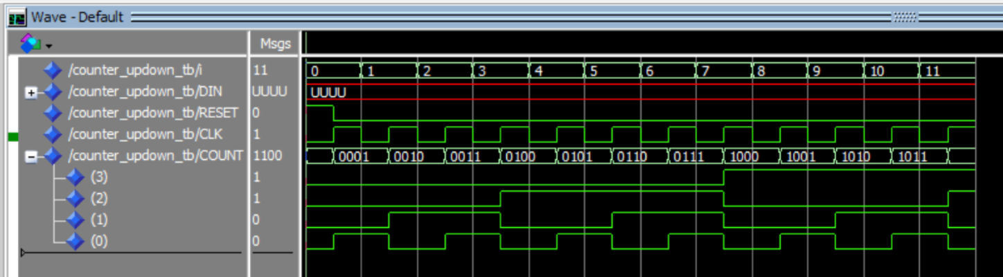
3.2.2 Example of Testbench for Sequential Circuit
For example, we want to make a testbench for this updown counter entity:
library IEEE;
use IEEE.std_logic_1164.all;
use IEEE.numeric_std.all;

entity counter_updown is
    Port (
        RESET, CLK, LD, UP : in std_logic;
        DIN                : in std_logic_vector (3 downto 0);
        COUNT              : out std_logic_vector (3 downto 0)
    );
end counter_updown;

architecture my_count of counter_updown is
    signal t_cnt : unsigned(3 downto 0); -- internal counter signal
begin
    process (CLK, RESET)
    begin
        if (RESET = '1') then
            t_cnt <= (others => '0'); -- clear
        elsif (rising_edge(CLK)) then
            if (LD = '1') then t_cnt <= unsigned(DIN); -- load
            else
                if (UP = '1') then t_cnt <= t_cnt + 1; -- incr
                else t_cnt <= t_cnt - 1; -- decr
                end if;
            end if;
        end if;
    end process;
    COUNT <= std_logic_vector(t_cnt);
end my_count;
In this case, the testbench combines the three architectural models that were previously explained. The Clock signal uses a process statement, while the Reset signal uses the simple assignment method. The other inputs are assigned directly in the declaration section because their values will not change.
Additionally, it is important to note the presence of the max_clk variable, which is used to limit the number of clock cycles run by the testbench. If the clock cycles are not limited, the testbench will continue to run indefinitely unless the program is stopped manually.
library ieee;
use ieee.std_logic_1164.all;
use ieee.numeric_std.all;

entity counter_updown_tb is
end counter_updown_tb;

architecture arch of counter_updown_tb is
    component counter_updown is
        Port (
            RESET, CLK, LD, UP : in std_logic;
            DIN                : in std_logic_vector (3 downto 0);
            COUNT              : out std_logic_vector (3 downto 0)
        );
    end component;

    constant period    : time := 20 ns;    -- clock period
    constant max_clk   : integer := 11;    -- maximum clock cycle
    signal cnt         : integer := 0;     -- clock cycle counter

    constant LD        : std_logic := '0';              -- input
    constant UP        : std_logic := '1';              -- input
    signal DIN         : std_logic_vector(3 downto 0);  -- input
    signal RESET       : std_logic;                     -- input
    signal CLK         : std_logic;                     -- input
    signal COUNT       : std_logic_vector(3 downto 0);  -- output

begin
    UUT : counter_updown port map (RESET, CLK, LD, UP, DIN, COUNT);

    -- reset = '1' at the first clock cycle, then change to '0'
    reset <= '1', '0' after period/2;

    CLK_generator : process
    begin
        CLK <= '0';
        wait for period/2;
        CLK <= '1';
        wait for period/2;

        if(cnt < max_clk) then cnt <= cnt + 1;
        else wait;
        end if;
    end process;
end arch;
Here is the simulation result of the testbench above:
4. Assert and Report Statement
4.1 Assert Statement
The assert statement is used for creating self-checking testbenches. It acts like an automated check that constantly monitors a condition. If the condition is false, it "asserts" a message, alerting us to a problem without requiring us to manually inspect the waveforms.
The full syntax of an assert statement is:
ASSERT condition REPORT "message" SEVERITY level;
ASSERT condition: This is the boolean expression that you expect to be true. For example,(actual_output = expected_output).REPORT "message": This is the message that gets printed to the simulator's console only if the condition is false. It's used to provide context about the failure.SEVERITY level: This is a crucial part of the statement that tells the simulator how to react to the failure.
For example, if we want to implement the assert statement in our testbench from section 3.1.2, we can implement it as below:
tb1: process
    constant period    : time := 20 ns;
    begin
        a <= '0';
        b <= '0';
        wait for period;

        assert ((sum = '0') and (carry = '0'))
        report "tes gagal pada testcase ke-1" severity error;

        a <= '0';
        b <= '1';
        wait for period;

        assert ((sum = '1') and (carry = '0'))
        report "tes gagal pada testcase ke-2" severity error;

        a <= '1';
        b <= '0';
        wait for period;

        assert ((sum = '1') and (carry = '0'))
        report "tes gagal pada testcase ke-3" severity error;

        a <= '1';
        b <= '1';
        wait for period;

        assert ((sum = '0') and (carry = '1'))
        report "tes gagal pada testcase ke-4" severity error;

        wait; -- wait until the end of time
    end process;
The following is the output produced by the testbench:

4.2 Severity Level
The severity level tells the simulator how serious the failed assertion is. There are four standard levels:
| Level | Description | Simulator Action |
|---|---|---|
NOTE |
Informational message. Used for debugging, tracing, or indicating progress. | Prints the message and continues simulation. |
WARNING |
Non-critical issue. Something is unexpected or out of spec, but the design might still function. | Prints a warning and continues simulation. Increments a warning counter. |
ERROR |
Functional failure. The design's output is incorrect. This is the standard for a failed test. | Prints an error and continues simulation. Increments an error counter. |
FAILURE |
Catastrophic/Fatal error. Something is fundamentally broken, making further simulation pointless. | Prints a failure message and immediately halts the simulation. |
Note that if we don't explicitly specify which severity level used in a report statement, it automatically defaults to note.
5. File I/O in VHDL
In VHDL, we can perform file handling using the TextIO library. This feature is very useful for documenting the results of a program that has been created. To use the TextIO library, we need to add it at the beginning of our program as follows:
use std.textio.all;
use ieee.std_logic_textio.all; -- For std_logic types
5.1 Read File
When repeatedly simulating a design, changing the value of each input one by one can be time-consuming and inefficient. Therefore, we can use a feature from the TextIO library that can read inputs from a file to be used in the design simulation.
Here is how to read input from a file in VHDL. First, we can define the file to be read within a process statement and open it in read_mode:
process
    -- Define the file and its open mode
    file text_file   : text open read_mode is "filename.txt";

    -- Variable to receive data from the file
    variable fileinp : integer;

    -- Line type variable to hold a row from the text file
    variable row     : line;

    -- Variale to store file reading status
    variable ok      : boolean
Then, we can read the file using the readline and read procedures from the TextIO library as follows:
begin
    while not endfile(text_file) loop --loop until the end of the text file
        readline(text_file, row); --reads the line from the file

        -- Skip empty lines or comments that start with '#'
        if row.all'length = 0 or row.all(1) = '#' then
            next;
        end if;

        -- Reads a variable from the line and puts it into fileinp
        read(row, fileinp, ok);

        assert ok
        report "Read 'sel' failed for line: " & row.all
        severity failure;  --report if the file read fails

        wait for delay; --delay for the read iteration
    end loop;
end process;
5.2 Write File
Besides reading a set of inputs to be used in a testbench, we can also use the TextIO library to save the results of our testbench to a file. This allows us to analyze the results without having to use a simulator like ModelSim or Vivado.
Here are the steps required to write the results of a testbench to a file. First, we can define the file to be created and open it in write_mode:
process
    -- Open "filename.txt" in write mode
    file text_file      : text open write_mode is "filename.txt";

    -- Line type variable to build a row for the text file
    variable row        : line;

    -- Variable holding the data to be written to the file
    variable data_write : integer;
Then, we can use the write and writeline procedures rom the TextIO library to write data to the file as follows:
begin
    -- writes data to the file, left-justified, 15 characters
    write(row, data_write, left, 15);

    writeline(text_file, row); -- writes the line to the file
end process;
Extra: Array in VHDL
6.1 Array
In VHDL, an array is a collection of elements that share the same data type. You can think of an array as a variable that holds many elements of the same type, and these elements are indexed to be accessed. The index can be a number or another indexable type, such as integer, natural, or std_logic_vector. Arrays can have one dimension (one-dimensional array) or more (two-dimensional, three-dimensional, and so on). Two-dimensional arrays are often used to represent tables or matrices.
6.2 Type
A type is a definition used to declare a new data type in VHDL. A type can be used to define complex data types, such as arrays or records, or as a type used to declare variables, ports, or signals. Types can also be used to describe the properties and structure of data.
VHDL has predefined data types, such as std_logic, std_logic_vector, integer, and others, but we can also create our own custom data types. Types that are predefined or embedded in VHDL libraries are called "built-in types," while types that we define ourselves are called "user-defined types."
Here is an example of using type and array to create a bank of 8-bit registers:
type RegisterArray is array (0 to 7) of std_logic_vector(7 downto 0);
signal registers : RegisterArray := (others => (others => '0'));
In the example above, we are defining a structure that could be used in an entity like a RegisterBank which has eight 8-bit registers. These registers are represented by the registers array, which has 8 elements, each with a length of 8 bits.