Module 9 - Microprogramming
- 1. Introduction: The Role of the Control Unit
- 2. The Control Unit Dilemma: Hardwired vs. Microprogrammed
- 3. Principles of Microprogrammed Control
- 4. The Micro-instruction
- 5. Execution Flow and Sequencing
1. Introduction: The Role of the Control Unit
-
1.1 Definition: The Control Unit (CU) is the core component of a computer's Central Processing Unit (CPU) that directs its operation. Often compared to the "brain" or "central nervous system" of the computer, the CU does not execute program instructions itself; rather, it manages and coordinates the activities of all other components, such as the Arithmetic Logic Unit (ALU) and the registers, to ensure instructions are performed correctly. It is the logical hub that orchestrates the complex sequence of events necessary for processing.
-
1.2 Function: The primary function of the Control Unit is to manage the fundamental operation of the CPU: the fetch-decode-execute cycle.
- Fetch: The CU generates the signals to read the memory address from the Program Counter (PC), send it to the Memory Address Register (MAR), and then read the instruction from RAM into the Instruction Register (IR).
- Decode: The CU interprets the binary opcode of the instruction that has been fetched into the IR.
- Execute: Based on the decoded instruction, the CU issues a precise sequence of control signals to the datapath (e.g., enabling registers, setting the ALU's operation, and managing memory access) to carry out the command.
-
1.3 The Problem: The mechanism for decoding instructions and generating these precise sequences of control signals presents a fundamental design choice. For a CPU to function, it must have a logic system capable of producing the correct set of outputs (control signals) for every possible input (opcode and status flags). The core design problem, therefore, is how to implement this complex logic. This challenge leads to two primary design philosophies: a fixed, high-speed logic circuit known as Hardwired Control, or a more flexible, memory-based approach known as Microprogrammed Control.
-
2. The Control Unit Dilemma: Hardwired vs. Microprogrammed
The fundamental problem of generating control signals, introduced in Section 1.0, is solved by two distinct design philosophies. This choice between a "hardwired" and a "microprogrammed" control unit represents a classic engineering trade-off between speed and flexibility.
-
2.1 Hardwired Control
-
Implementation: A hardwired control unit is a fixed, sequential logic circuit. Its logic is built directly from gates (AND, OR, NOT) and flip-flops, which together form a complex Finite State Machine (FSM). The 4-bit
opcodefrom the instruction, along with status flags and the current state, are fed into this combinatorial logic, which in turn generates the specific output signals (RAI,PCO,SUB, etc.) for that clock cycle. -
Analogy: This design is analogous to a custom-built, high-speed machine designed for one specific task, like a specialized factory robot. It is built from the ground up to perform its one job as fast as possible.
-
Pros: Its primary advantage is speed. Because the control signals are generated directly by logic gates, the propagation delay is minimal, allowing for a very high clock speed.
-
Cons: The design is extremely inflexible. If a bug is found or a new instruction needs to be added (e.g., adding a
SUBinstruction to a CPU that only hasADD), the entire logic circuit must be redesigned, re-manufactured, and replaced. This makes it complex to design and nearly impossible to modify or upgrade.
-
-
2.2 Microprogrammed Control
-
Implementation: This is the alternative, flexible, memory-based approach. In this design, the Control Unit is not a complex web of gates but rather a small, simple "computer-within-a-computer." This internal computer has its own simple program (a microprogram) stored in a special, high-speed memory called a Control Store.
-
Analogy: Instead of a custom-built robot, this is like a general-purpose, programmable robot. To execute a command like "ADD," it runs a small, internal program (a "micro-routine") that tells it, step-by-step, how to activate the necessary hardware components to perform the addition.
-
Pros: The primary advantage is flexibility. To add a new instruction, one simply adds a new micro-routine to the Control Store's memory (firmware). This makes the design process systematic and far easier to debug and upgrade.
-
Cons: Its main disadvantage is speed. It is inherently slower than a hardwired unit because it must perform an extra memory access (fetching the micro-instruction from the Control Store) for every clock cycle.
-
-
2.3 Comparison Table
| Feature | Hardwired Control (FSM) | Microprogrammed Control |
|---|---|---|
| Implementation | Sequential logic circuit (gates, flip-flops) | Control Store (ROM) & Sequencer |
| Speed | Very Fast (low propagation delay) | Slower (extra memory access) |
| Flexibility | Very Low. Difficult to modify. | Very High. Can be updated (firmware). |
| Design Complexity | High, error-prone, and complex to manage. | Systematic, orderly, and easier to debug. |
| Best For | RISC (Reduced Instruction Set Computers) | CISC (Complex Instruction Set Computers) |
3. Principles of Microprogrammed Control
This section details the core theory of the microprogrammed control unit, the flexible alternative to the hardwired FSM. This approach fundamentally changes the design from a complex, fixed logic circuit to a simple, programmable one.
-
3.1 Core Concept: The "Computer-within-a-Computer"
- The most effective analogy for a microprogrammed control unit is that it is a "computer-within-a-computer." The main CPU (which has assembly instructions like
ADD,LDA,JMP) is the "outer" computer. The Control Unit itself is a tiny, hidden, "inner" computer. - This inner computer has its own simple program, called a microprogram. The microprogram is composed of a sequence of instructions called micro-instructions.
- The key relationship is this: One assembly instruction (like
LDA) is interpreted by the CU as a command to run a specific micro-routine (a "subroutine" of micro-instructions). The micro-routine is the step-by-step recipe that defines how to execute that single assembly instructior.
- The most effective analogy for a microprogrammed control unit is that it is a "computer-within-a-computer." The main CPU (which has assembly instructions like
-
3.2 Architectural Components
-
To function as a simple computer, the microprogrammed CU has its own set of internal hardware components, separate from the main datapath.
-
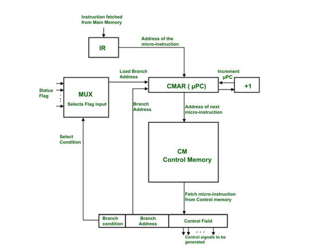
3.2.1 Control Store (or Control Memory):
- This is a small, high-speed Read-Only Memory (ROM) that is located inside the Control Unit.
- Its sole purpose is to store the entire microprogram—that is, all the micro-routines for every assembly instruction in the CPU's instruction set (e.g., the routines for
LDA,STA,ADD,JMP, etc.).
-
3.2.2 Micro-Sequencer (Next Address Logic):
- This is the "Program Counter" for the Control Unit (often called a
uPCor "micro-Program Counter"). - Its job is to determine the address of the next micro-instruction to be fetched from the Control Store.
- It decides this address based on several inputs: the main instruction's
opcode(for the initial "decode" jump), CPU status flags (for conditional branches likeJEQ), and sequencing fields from the current micro-instruction (e.g.,SEQ_NEXT,SEQ_FETCH).
- This is the "Program Counter" for the Control Unit (often called a
-
3.2.3 Micro-instruction Register (uIR):
- This is a register that holds the current micro-instruction that was just fetched from the Control Store.
- This is the most critical component for execution: the output bits of this register are the actual control signals that are sent to the datapath.
- For example, a 16-bit
uIRmight directly output 16 control signals (likeRegister_Enable,ALU_Subtract,Memory_Write, etc.) to the rest of the CPU.
-
4. The Micro-instruction
If the Control Store is the "recipe book" for the CPU, then a micro-instruction is a single "line" in that recipe. It is the most fundamental unit of control in a microprogrammed CPU, defining the exact set of hardware operations that will occur in a single clock cycle.
-
4.1 Definition A micro-instruction is a single word fetched from the Control Store. Its primary function is to specify the control signals to be generated for one clock tick. Each micro-instruction is held in the Micro-instruction Register (uIR), and the bits of this register are used—either directly or after decoding—to activate or deactivate every control line in the CPU's datapath [1].
-
4.2 Format and Fields While the exact layout varies, a micro-instruction is typically divided into two primary types of fields [2].
-
4.2.1 Control Field: This is the main part of the micro-instruction. It contains the bits that directly control the datapath components. For example, a "1" in a specific bit position might enable a register to output its value to the main bus (like
RAO), while a "0" keeps it disabled. Another set of bits might specify the operation for the ALU (e.g.,SUB=1). -
4.2.2 Sequencing Field (Next Address Field): This field doesn't control the datapath; it controls the Micro-Sequencer itself. These bits provide the sequencer with information to determine the address of the next micro-instruction. This field might contain:
- A specific "next address" to jump to.
- A "branch condition" code (like
SEQ_DECODEorSEQ_JUMP_ON_ZERO) that tells the sequencer how to find the next address by checking opcodes or status flags [3].
-
-
4.3 Horizontal vs. Vertical Microprogramming The "Control Field" can be designed in two primary ways, which presents a classic trade-off between speed and memory efficiency [4].
-
4.3.1 Horizontal Microprogramming: This is a "decoded" or "unencoded" approach. The micro-instruction is very wide, and each bit in the control field corresponds directly to a single control line. If the CPU has 60 control signals, the control field is 60 bits wide.
- Pros: It is extremely fast. No additional decoding logic is needed; the bits from the uIR can be used directly. It also allows for high parallelism, as many signals can be activated in the same cycle.
- Cons: It is very inefficient. A micro-instruction that only activates 2 signals (e.g.,
RAOandRBI) still requires the full 60 bits, wasting space in the Control Store.
-
4.3.2 Vertical Microprogramming: This is an "encoded" approach. Instead of one bit per signal, groups of signals are encoded into fields. For example, if an ALU has 8 possible operations (ADD, SUB, AND, OR, etc.), a 3-bit field (
2^3 = 8) can be used to select which operation to perform.- Pros: It is highly efficient and saves a significant amount of space in the Control Store. The micro-instructions are much narrower.
- Cons: It is slower. The encoded fields (like the 3-bit ALU field) must be passed through an external decoder circuit to generate the final control signals, adding a layer of gate delay.
In practice, most modern designs are a hybrid, using vertical encoding for mutually exclusive signals (like ALU operations) and horizontal bits for independent signals (like
Memory_Write). -
5. Execution Flow and Sequencing
This section connects all the previous concepts to illustrate how the microprogrammed control unit runs a program. The core of this operation is the mapping of high-level assembly instructions to low-level micro-routines, all managed by the micro-sequencer.
- 5.1 Mapping Assembly to Micro-routines
-
The most important relationship in this design is the one-to-many mapping between an assembly instruction and its micro-routine. The main CPU's instruction set (the "assembly language") is not executed directly by the hardware; rather, each assembly instruction's opcode is a command that tells the micro-sequencer to find and run a specific "subroutine" of micro-instructions stored in the Control Store.
-
Hypothetical Example:
- Consider a CPU with registers
R0,R1, aPC,MAR,IR, andRAM. - A programmer writes the assembly instruction:
LOAD R0, [0x30] - This translates to the 8-bit machine code
0001 0011(Opcode0001forLOAD R0, and Address0011for0x30). - The Control Unit is designed to interpret this
0001opcode. This single assembly instruction triggers a multi-step micro-routine:
- Consider a CPU with registers
-
| Phase | Micro-operation | Keterangan |
|---|---|---|
| Fetch | uAddr 0: PC_out, MAR_in |
(Fetch CC1) Send PC to memory. |
uAddr 1: RAM_out, IR_in |
(Fetch CC2) Get instruction 00010011 into IR. |
|
| Decode | uAddr 1: (Sequencer Logic) |
Sequencer sees 0001, maps it to uAddr 16. |
| Execute | uAddr 16: IR_addr_out, MAR_in |
(Execute CC1) Get address 0011 from IR. |
uAddr 17: RAM_out, R0_in, PC_inc |
(Execute CC2) Get data from RAM[0x30] into R0. Increment PC. |
|
uAddr 17: (Sequencer Logic) |
Sequencer sees SEQ_FETCH, sets next_uPC = 0. |
-
5.2 The Fetch-Decode-Execute Cycle (Microprogram View)
-
From the micro-sequencer's perspective, the fetch-decode-execute cycle is a continuous loop of branching within its own Control Store [2].
-
1. Fetch: The micro-sequencer is hardwired to always start at a fixed address (e.g.,
uAddr 0) when a new instruction is needed. It then executes theFetchmicro-routine (e.g., atuAddr 0anduAddr 1). -
2. Decode: The final micro-instruction of the
Fetchroutine (atuAddr 1in our example) contains a specialSEQ_DECODEsequencing command. This command tells the micro-sequencer to stop incrementing and instead use theopcodefrom theIRas an input to its logic. This logic acts as a "mapping ROM," translating the opcode (e.g.,0001) into the starting address of its corresponding micro-routine (e.g.,uAddr 16). -
3. Execute: The micro-sequencer jumps to that new address (e.g.,
uAddr 16) and executes the micro-routine for the instruction. The final micro-instruction of that routine (e.g., atuAddr 17) then issues aSEQ_FETCHcommand, which forces the micro-sequencer to jump back touAddr 0and begin the entire process again for the next assembly instruction.
-
-
5.3 Conditional Branching (Sequencing with Flags)
-
The true power of a micro-sequencer is revealed in how it handles conditional branching (e.g.,
JUMP_IF_ZERO). This is not implemented with a new micro-instruction, but by adding logic to the sequencer'sDecodestep. -
The
SEQ_DECODEcommand is enhanced to not only look at theopcodebut also at the CPU'sStatus Flags(likeZero_FlagandCarry_Flag). -
Example (Hypothetical
JUMP_ZERO [ADDR], Opcode1010):- The programmer writes
CMP R0, R1(which sets theZero_Flag) followed byJUMP_ZERO 0x05. - When the
JUMP_ZEROinstruction (1010 0101) is fetched, the micro-sequencer'sDECODElogic executes the following:
if (opcode == "1010") then -- This is a JUMP_ZERO instruction if (Zero_Flag == '1') then next_uPC = uAddr_JUMP_ROUTINE; -- Jump to the JUMP micro-routine else next_uPC = uAddr_NOP_ROUTINE; -- Jump to the NOP micro-routine (to just inc PC) end if; else -- (handle other opcodes...) end if; - The programmer writes
-
In this way, the micro-sequencer dynamically selects the correct micro-routine—either
JMPorNOP—based on the current state of the CPU flags, effectively executing the conditional branch.
-
-
5.4 VHDL Code Example: A Hypothetical Microprogrammed Control Unit
The following VHDL code is a complete, behavioral model of a hypothetical microprogrammed control unit. This example is simplified to clearly demonstrate the core concepts of sequencing, mapping, and conditional branching.
This code directly illustrates the concepts from sections 5.1, 5.2, and 5.3.
- Mapping (5.1): The
init_romfunction shows how opcodes (like"0001") are "mapped" to the starting addresses of micro-routines (likeuAddr 20). - Fetch/Decode/Execute (5.2): The
next_uPCprocess (the Micro-Sequencer) implements this flow.SEQ_FETCH(atuAddr 0, 1) is theFetchphase.when SEQ_DECODE =>is theDecodephase, which reads theOPCODE_IN.- The resulting jump (e.g.,
next_uPC <= to_unsigned(20, 8)) is the start of theExecutephase.
- Conditional Branching (5.3): The
SEQ_DECODEblock contains the most important logic. It explicitly checks theZ_FLAGin addition to theOPCODE_INto implement aJUMP_IF_ZEROinstruction.
library IEEE;
use IEEE.std_logic_1164.all;
use IEEE.numeric_std.all;

entity Hypothetical_Micro_CU is
    port (
        CLK         : in  std_logic;
        RST         : in  std_logic;

        -- Inputs from Datapath
        OPCODE_IN   : in  std_logic_vector(3 downto 0);
        Z_FLAG      : in  std_logic; -- (for conditional jumps)

        -- Outputs to a hypothetical 10-signal datapath
        PC_OUT      : out std_logic := '0';
        PC_INC      : out std_logic := '0';
        MAR_IN      : out std_logic := '0';
        RAM_OUT     : out std_logic := '0';
        RAM_IN      : out std_logic := '0';
        IR_IN       : out std_logic := '0';
        ACC_IN      : out std_logic := '0';
        ACC_OUT     : out std_logic := '0';
        TEMP_IN     : out std_logic := '0';
        ALU_OUT     : out std_logic := '0'
    );
end entity;

architecture Behavioral of Hypothetical_Micro_CU is

    -- 3.2.2 Micro-Sequencer
    -- This is the "micro-Program Counter" (uPC)
    signal uPC      : unsigned(7 downto 0) := (others => '0');
    signal next_uPC : unsigned(7 downto 0);

    -- 3.2.3 Micro-instruction Register (uIR)
    -- 10 control bits + 2 sequencing bits
    signal uIR : std_logic_vector(11 downto 0);

    -- 4.2.2 Sequencing Field Constants
    constant SEQ_NEXT   : std_logic_vector(1 downto 0) := "00";
    constant SEQ_DECODE : std_logic_vector(1 downto 0) := "01";
    constant SEQ_FETCH  : std_logic_vector(1 downto 0) := "10";
    constant SEQ_HLT    : std_logic_vector(1 downto 0) := "11";

    -- 4.2 Format and Fields
    constant C_SEQ_BITS  : integer := 2;
    constant C_CTRL_BITS : integer := 10;
    constant C_UCODE_WIDTH : integer := C_SEQ_BITS + C_CTRL_BITS; -- 12 bits

    -- 3.2.1 Control Store (ROM)
    type t_control_store is array(0 to 255) of std_logic_vector(C_UCODE_WIDTH - 1 downto 0);

    -- Helper function to build a micro-instruction
    function to_ucode(
        ctrl : std_logic_vector(C_CTRL_BITS - 1 downto 0);
        seq  : std_logic_vector(C_SEQ_BITS - 1 downto 0)
    ) return std_logic_vector is
    begin
        return seq & ctrl; -- [Seq(1:0), Ctrl(9:0)]
    end function;

    -- Initialize the Control Store (ROM) with micro-routines
    function init_rom return t_control_store is
        variable rom : t_control_store := (others => (others => '0'));

        -- Control Field constants (10 bits)
        -- [PC_OUT, PC_INC, MAR_IN, RAM_OUT, RAM_IN, IR_IN, ACC_IN, ACC_OUT, TEMP_IN, ALU_OUT]
        constant C_FETCH1 : std_logic_vector(9 downto 0) := "1010000000"; -- PC_OUT, MAR_IN
        constant C_FETCH2 : std_logic_vector(9 downto 0) := "0001010000"; -- RAM_OUT, IR_IN
        constant C_LDA1   : std_logic_vector(9 downto 0) := "0010000000"; -- MAR_IN (assume from IR)
        constant C_LDA2   : std_logic_vector(9 downto 0) := "0101001000"; -- PC_INC, RAM_OUT, ACC_IN
        constant C_JUMP1  : std_logic_vector(9 downto 0) := "0000000000"; -- (Assume PCI/IRO logic)
        constant C_NOP1   : std_logic_vector(9 downto 0) := "0100000000"; -- PC_INC

    begin
        -- 5.2 Fetch Cycle
        rom(0) := to_ucode(C_FETCH1, SEQ_NEXT);   -- uAddr 0
        rom(1) := to_ucode(C_FETCH2, SEQ_DECODE); -- uAddr 1

        -- 5.1 Mapping Assembly to Micro-routines
        -- These are the "Execute" routines

        -- Map Opcode "0001" (LOAD_ACC) to uAddr 20
        rom(20) := to_ucode(C_LDA1, SEQ_NEXT);
        rom(21) := to_ucode(C_LDA2, SEQ_FETCH);

        -- Define targets for conditional branches
        rom(16) := to_ucode(C_NOP1, SEQ_FETCH);  -- uAddr 16 (NOP routine)
        rom(30) := to_ucode(C_JUMP1, SEQ_FETCH); -- uAddr 30 (JUMP routine)

        -- ... the rest of the ROM for other opcodes (ADD, STA, etc.) ...

        return rom;
    end function;

    -- Create the constant ROM
    constant Control_Store : t_control_store := init_rom;

    -- Define the jump targets for conditional branches
    constant uAddr_NOP_ROUTINE : unsigned(7 downto 0) := to_unsigned(16, 8);
    constant uAddr_JMP_ROUTINE : unsigned(7 downto 0) := to_unsigned(30, 8);

begin

    -- 1. Micro-Program Counter (uPC) Register (The "State")
    process(CLK)
    begin
        if rising_edge(CLK) then
            if RST = '1' then
                uPC <= (others => '0'); -- On reset, go to Fetch (uAddr 0)
            else
                uPC <= next_uPC;
            end if;
        end if;
    end process;

    -- 2. ROM Read (Concurrent)
    uIR <= Control_Store(to_integer(uPC));

    -- 3. Micro-Sequencer (Next uPC Logic)
    -- This process is the "brain" of the Control Unit
    process(uPC, uIR, OPCODE_IN, Z_FLAG)
        variable seq_control : std_logic_vector(1 downto 0);
    begin
        seq_control := uIR(C_UCODE_WIDTH - 1 downto C_CTRL_BITS);

        -- Default: always increment
        next_uPC <= uPC + 1;

        case seq_control is
            when SEQ_NEXT =>
                next_uPC <= uPC + 1;

            when SEQ_FETCH =>
                next_uPC <= (others => '0'); -- Go back to Fetch (uAddr 0)

            when SEQ_HLT =>
                next_uPC <= uPC; -- Halt by looping on this address

            when SEQ_DECODE =>
                -- This is the 5.2 Decode step
                -- It maps the opcode to a micro-routine address
                case OPCODE_IN is
                    when "0001" => -- LOAD_ACC
                        next_uPC <= to_unsigned(20, 8);

                    -- ... other non-branching opcodes (ADD, STA, etc.) ...

                    -- 5.3 Conditional Branching Logic
                    when "1010" => -- JUMP_IF_ZERO
                        if Z_FLAG = '1' then
                            next_uPC <= uAddr_JMP_ROUTINE;
                        else
                            next_uPC <= uAddr_NOP_ROUTINE;
                        end if;

                    -- ... other conditional branches (JNE, JLT, etc.) ...

                    when others =>
                        next_uPC <= uAddr_NOP_ROUTINE; -- Invalid opcode
                end case;

            when others =>
                next_uPC <= (others => '0'); -- Safe state
        end case;
    end process;

    -- 4. Output Logic (Concurrent)
    -- Map the 10 control bits from the uIR to the output ports
    PC_OUT  <= uIR(9);
    PC_INC  <= uIR(8);
    MAR_IN  <= uIR(7);
    RAM_OUT <= uIR(6);
    RAM_IN  <= uIR(5);
    IR_IN   <= uIR(4);
    ACC_IN  <= uIR(3);
    ACC_OUT <= uIR(2);
    TEMP_IN <= uIR(1);
    ALU_OUT <= uIR(0);

end Behavioral;