Digital Sistem Design (PSD/DSG)
- Module 1 - Setup
- Vivado Installation Tutorial
- Vivado Simulation and Synthesis Tutorial
- Quartus Prime Installation Tutorial
- Quartus Prime Synthesis Tutorial
- ModelSim Installation Tutorial
- ModelSim Simulation Tutorial
- Module 2 - Dataflow Style
- Module 3 - Behavioural Style
- Understanding Behavioral Style
- Process Statement
- Sequential Statement
- Wait Statements
- Report Statements
- Module 4 - Testbench
- 1. Understanding Testbench in VHDL
- 2. Components of a Testbench
- 3. Testbench Architecture Models
- 4. Assert and Report Statement
- 5. File I/O in VHDL
- Extra: Array in VHDL
- Module 5 - Structural Programming
- Module 6 - Looping Construct
- Introduction to Looping Constructs
- For Loop
- While Loop
- Loop Control - Next & Exit
- For-Generate Loop
- When & Which
- Module 7 - Procedure, Function, and Impure Function
- Procedure
- Function
- Impure Function
- Procedure, Function and Impure Function Synthesis
- Difference between Procedure, Function and Impure Function
- Module 9 - Microprogramming
- 1. Introduction: The Role of the Control Unit
- 2. The Control Unit Dilemma: Hardwired vs. Microprogrammed
- 3. Principles of Microprogrammed Control
- 4. The Micro-instruction
- 5. Execution Flow and Sequencing
- Module 10 - Final Project
Module 1 - Setup
For Digital Sistem Design (DSG) or Perancangan Sistem Digital (PSD) Practicum, students must have already installed between Vivado only or ModelSim + Quartus Prime
Vivado Installation Tutorial
1.1 Vivado Explanation
Vivado is an Integrated Design Environment (IDE) developed by Xilinx (now AMD) used for designing, simulating, and implementing digital circuits on FPGAs (Field-Programmable Gate Arrays). It serves as the primary software tool to take a VHDL hardware description and turn it into a functional circuit on a physical chip. Vivado itself is a complete, integrated workshop for Xilinx FPGAs. It has all the tools you need (design, simulation, implementation) under one roof.
Before choosing Vivado be cautious that Vivado requires atleast 60gb of storage and a demanding CPU performance.
1.2 Vivado Installation
To install Vivado, please follow this link and proceed to do the next procedure until finished.
Step 1 : Download the Vivado Installer
Go into Vivado Archive and choose version 2022.2.
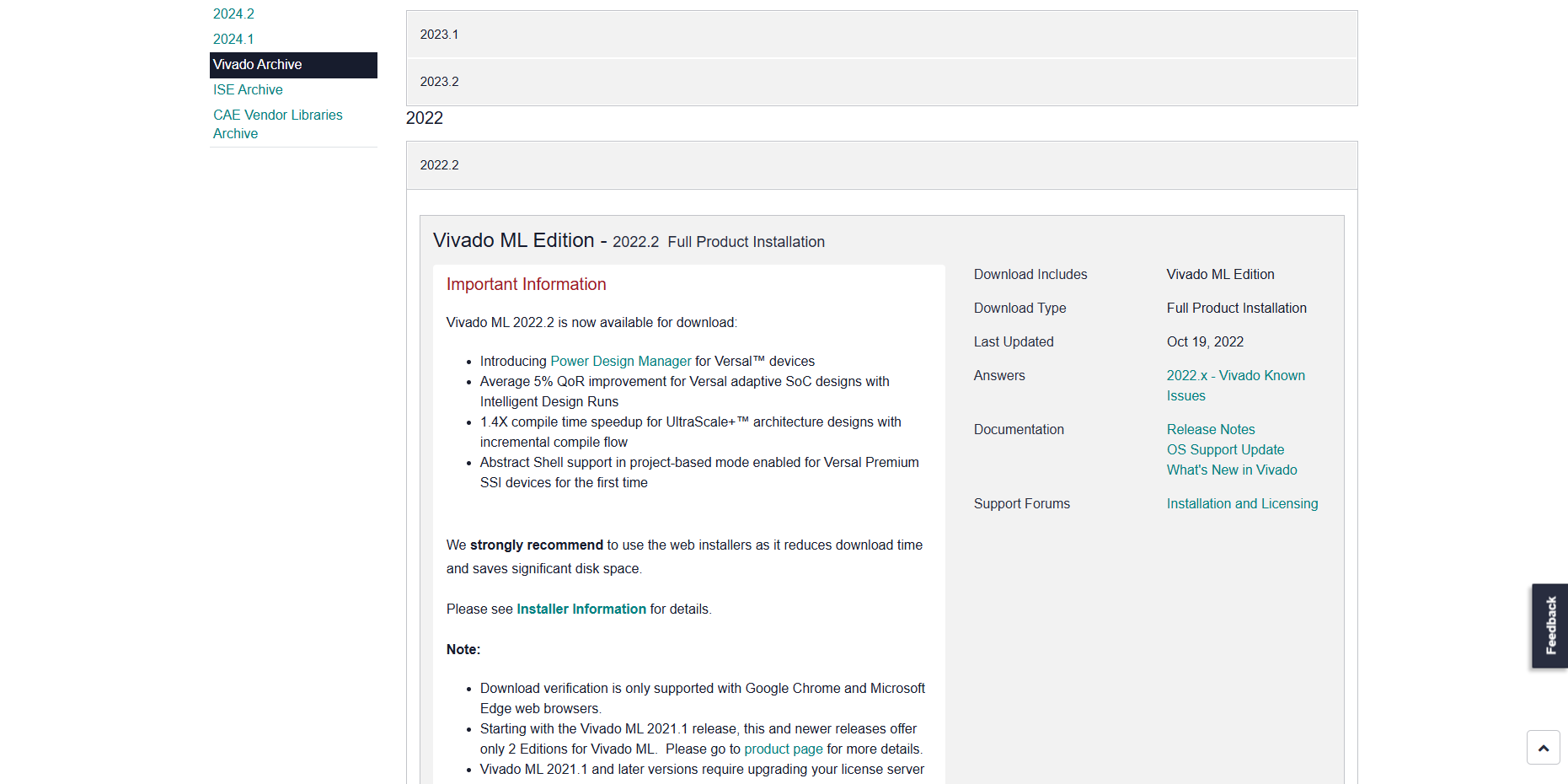
Then Scroll and choose Windows version and then click the link

The link will take you into a login page, you may create a new account or if you already had one you can just log into your AMD account.

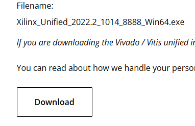
The page will take you into the download center where you will fill out your information, you may just fill up only the required part to download the installer. After filling all your information, you can just download the installer on the bottom of the page.
Step 2 : Install the Vivado
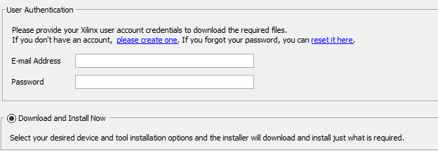
Run the installation file

Proceed to log into the same account you've just logged into/created before in step 1 and then just choose Download and install now and proceed into the next step
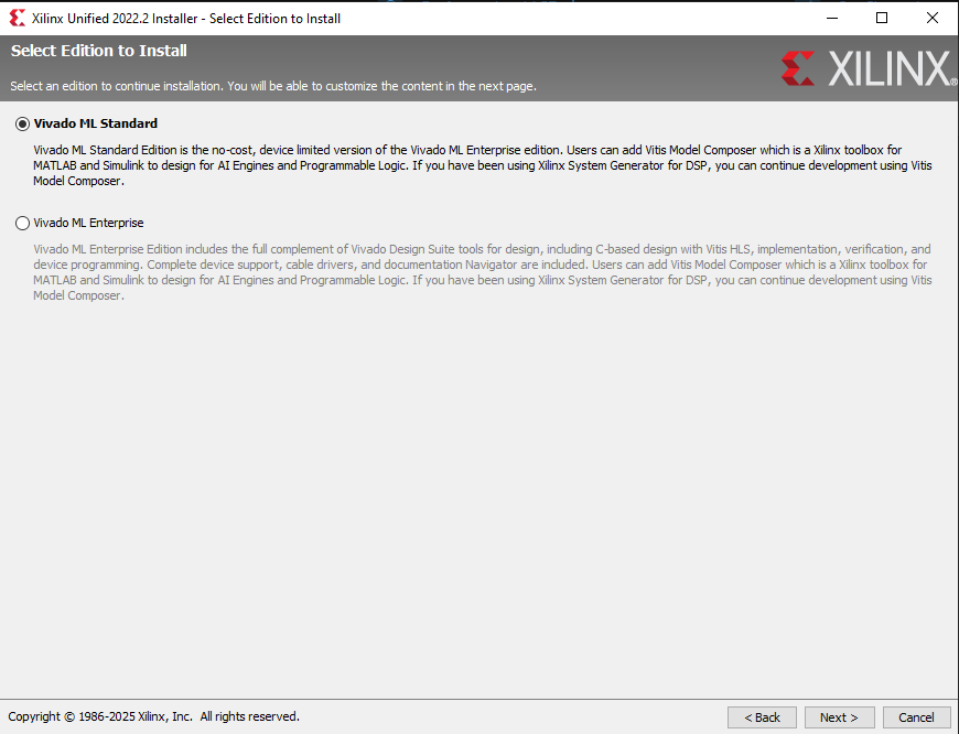
Choose Vivado and then proceed
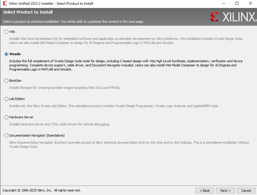
Choose Vivado ML Standard and proceed
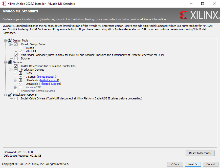
Just Check every box like in the screenshot below and make sure to have enough disk space required on the bottom left and then ou may proceed.
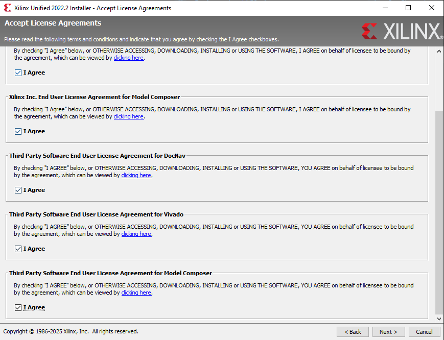
Just check all the agree box and you may proceed
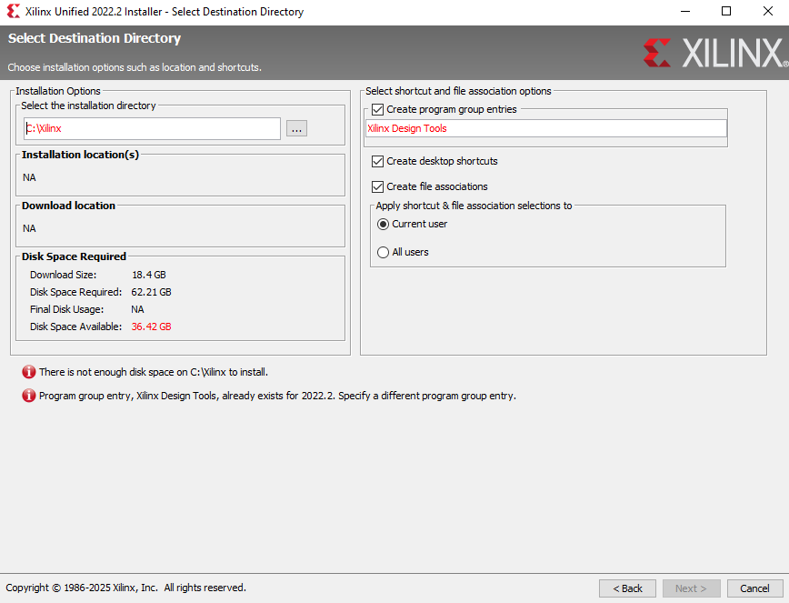
Choose where you want Vivado to be installed and then you may proceed to the installation part
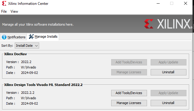
Wait until the installation is completed and then you may check in xilinx information center if the Vivado installation had completed. Make sure to check if the Version you've installed is correct.

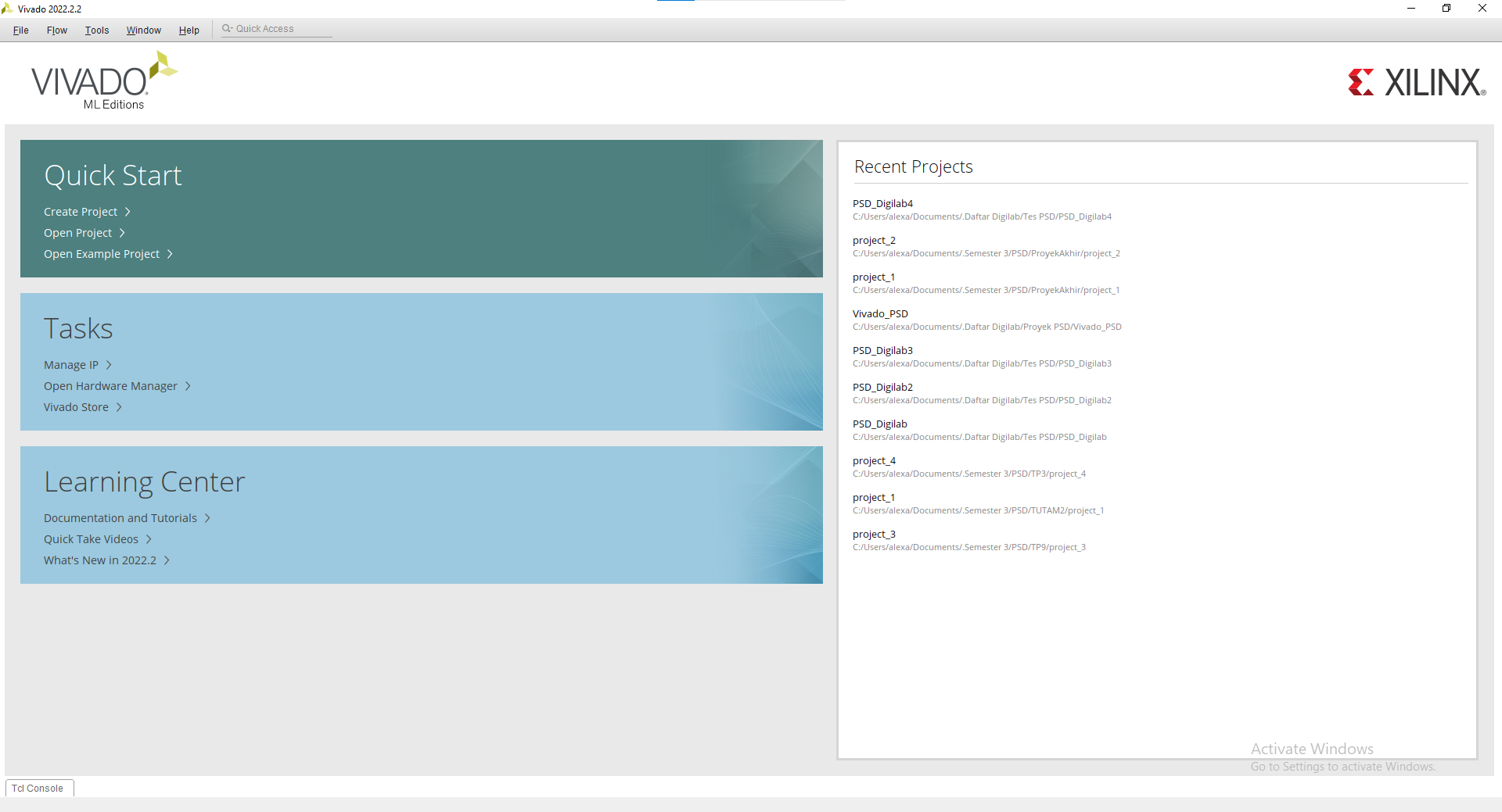
You may open Vivado and voila you've installed Vivado

Vivado Simulation and Synthesis Tutorial
1.3 Vivado Tutorial
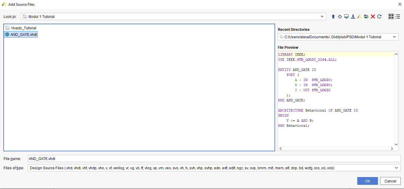
For this tutorial, we will use this code for reference :
LIBRARY IEEE;
USE IEEE.STD_LOGIC_1164.ALL;

ENTITY AND_GATE IS
    PORT (
        A : IN  STD_LOGIC;
        B : IN  STD_LOGIC;
        Y : OUT STD_LOGIC
    );
END AND_GATE;

ARCHITECTURE Behavioral OF AND_GATE IS
BEGIN
    Y <= A AND B;
END Behavioral;
1.3.1 Creating a new Vivado file
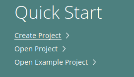
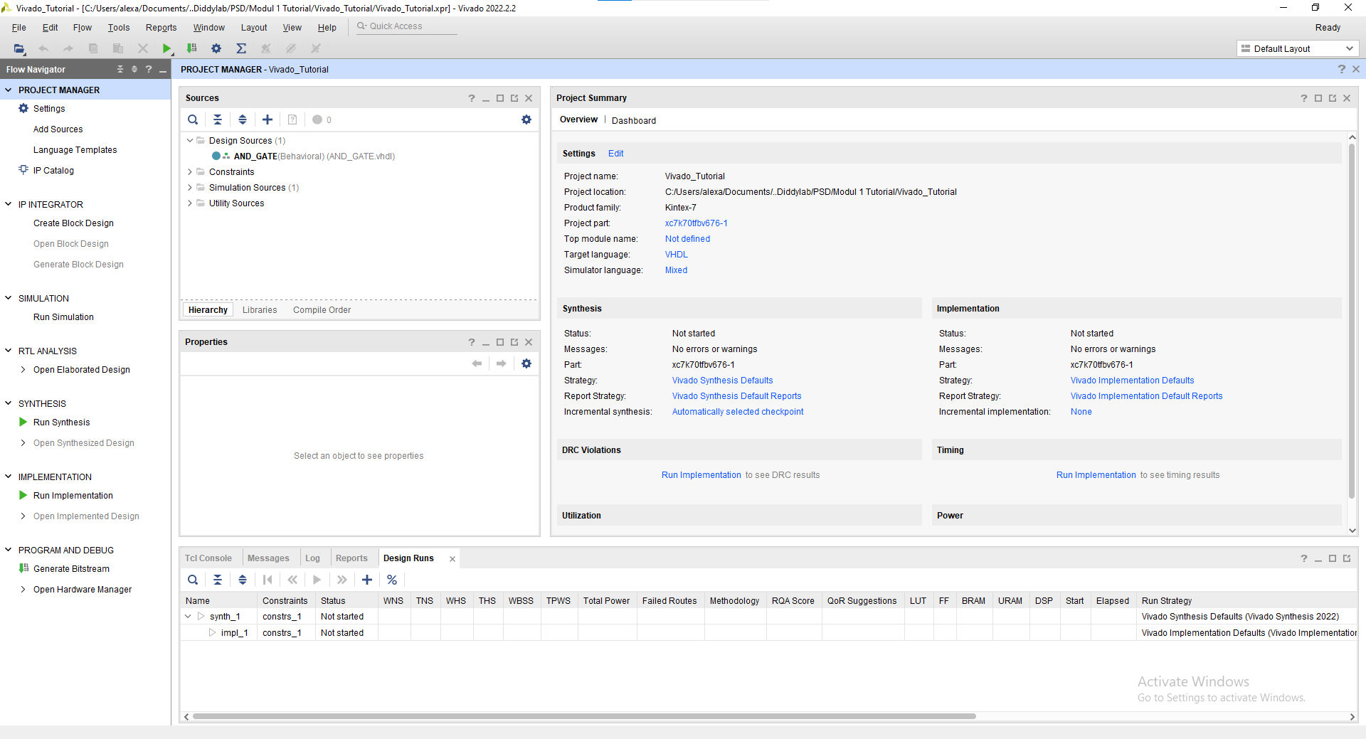
Create a new project
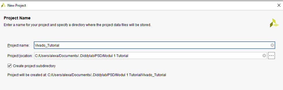
Enter your project name and where you want it to be saved
Choose RTL Project
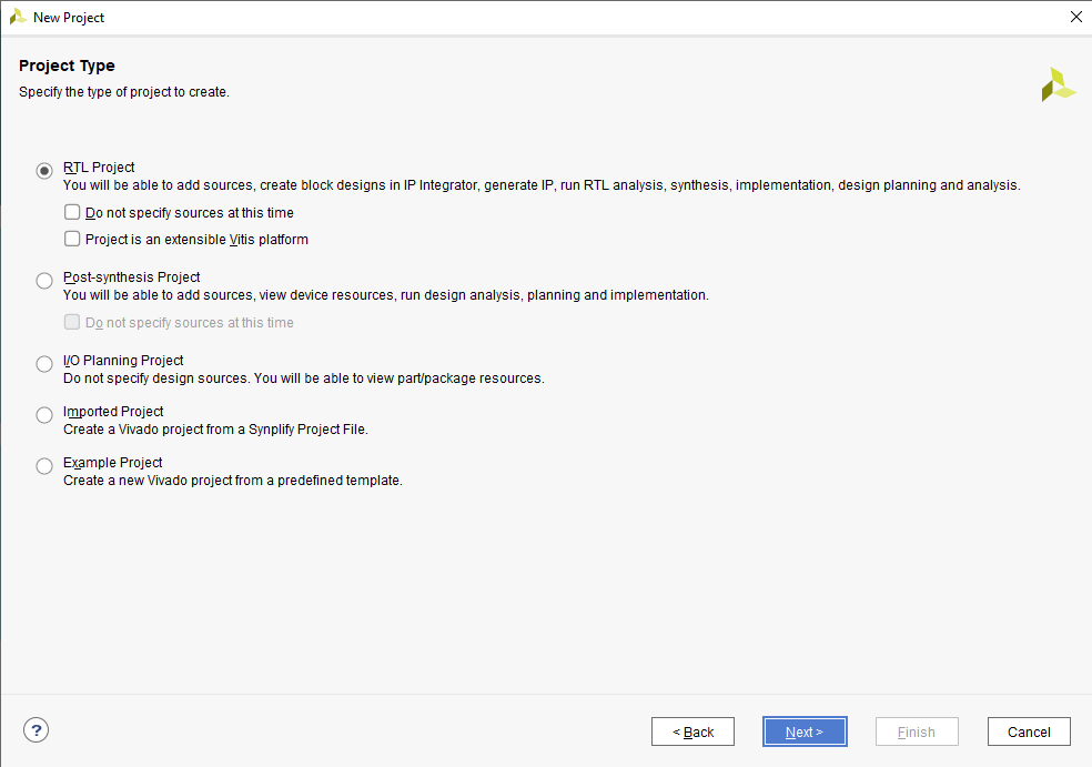
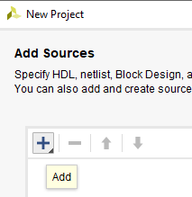
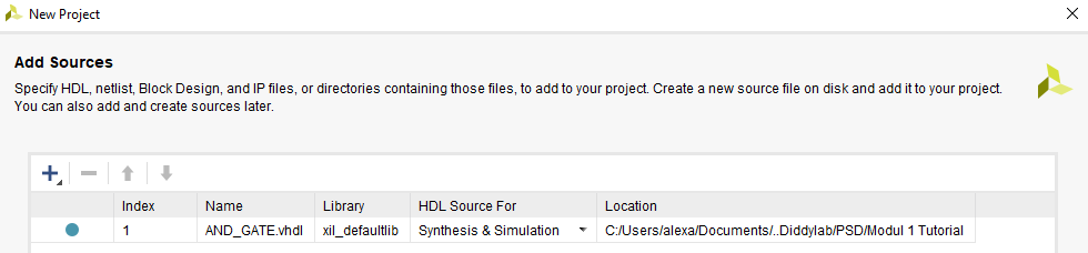
Change the target language into VHDL and add your VHDL code into the project

You may skip the add constraints page and also the default part proceed into the project creation. Finally you've created a new project and this will be your screen now.
1.3.2 Simulation Tutorial
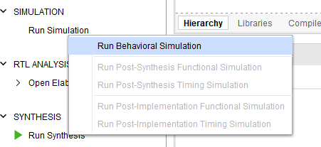
Click "Run Simulation" on the left part of the screen. And choose "Run Behavorial Simulation"
If there's any error warning, you may read and fix the error before proceeding into the simulation.
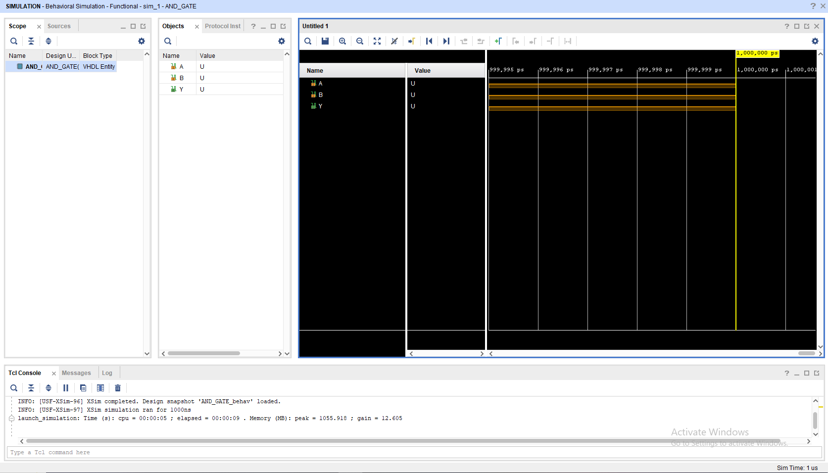
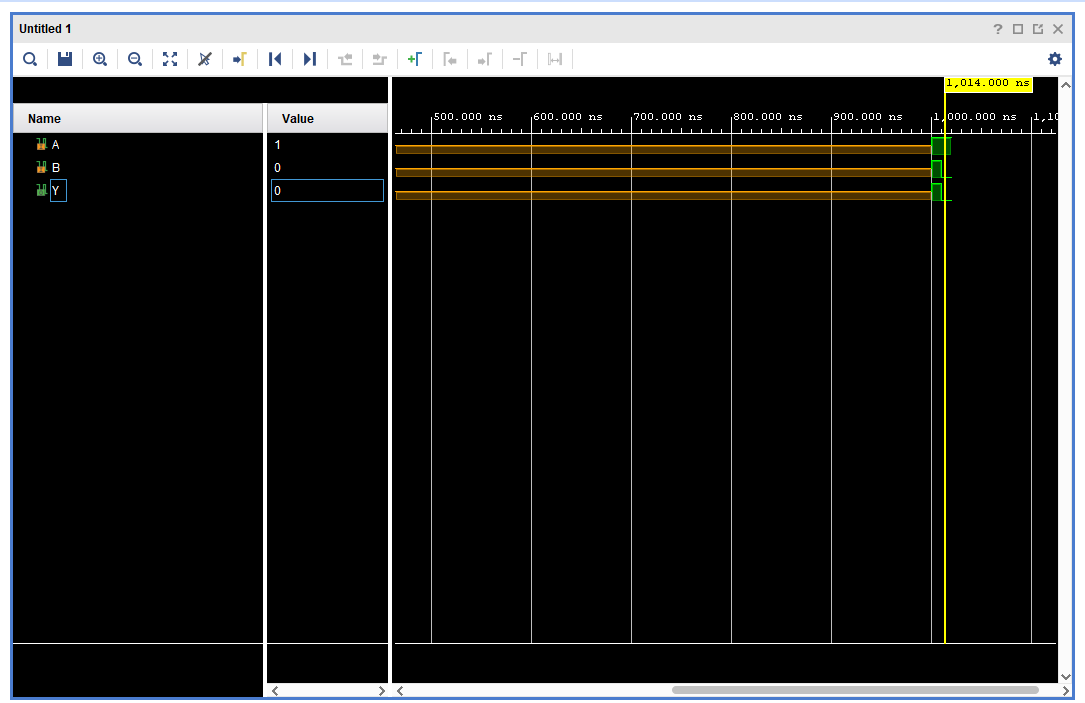
This will be your screen after you run the simulation.
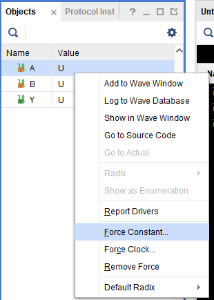
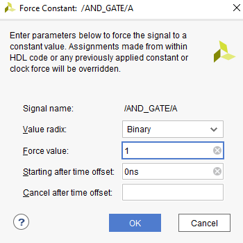
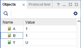
To add a signal, you may change the value in the objects part, choose "Force Constant" and change according to what you want to do. Remember to change the INPUT not the OUTPUT
After changing the Value you may click the "Run for 10ns" on the top bar
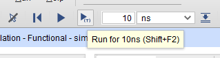
You may see that there's a new signal after you press the button
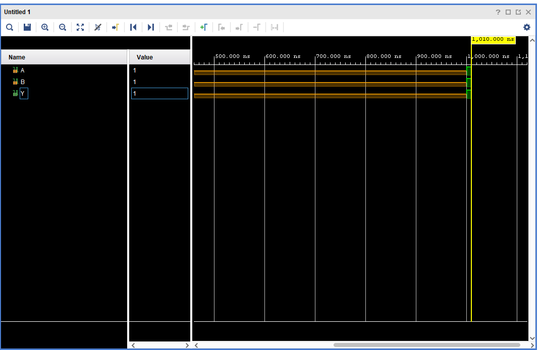
You may also move the yellow line with your cursor to switch to a different period of time on the waveform
NOTE : All of this is just a manual simulation tutorial. There are a way to do this automatically (Hint: Module 4).
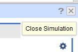
To close simulation, you may click the top right button
1.3.3 Synthesis Tutorial
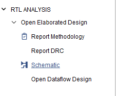
Go to the "RTL Analysis" and run "Schematic" and if there's a notification just select "ok"
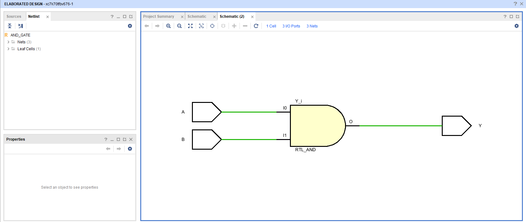
Wait until the elaborated design is finished and then you may see your VHDL code schematic.
Quartus Prime Installation Tutorial
1.1 Quartus Prime Explanation
Intel Quartus Prime is a comprehensive software suite from Intel used for designing, synthesizing, and programming programmable logic devices (PLDs), such as Field-Programmable Gate Arrays (FPGAs) and Complex Programmable Logic Devices (CPLDs). The software provides a complete integrated development environment (IDE) for digital circuit engineers and designers.
1.2 Quartus Prime Installation
To install Quartus Prime, please follow this link and proceed to do the next procedure until finished.
Step 1 : Download the Quartus Prime Installer
Go into Multiple Download and then download the Intel Quartus Prime installer :

The link will take you into an software license agreement, just accept the terms and proceed with the download.
Step 2 : Install the Quartus Prime
Extract the zip and then Run the installation file setup.

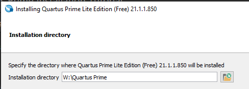
If the installer ask you to accept the agreement just accept and proceed with the next part. And then choose the directory for where you want the Quartus Prime to be installed.
NOTE : Do not use space in the folder naming.
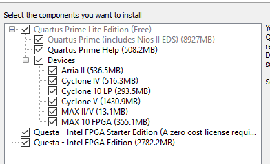
Check every components and proceed with the installation.
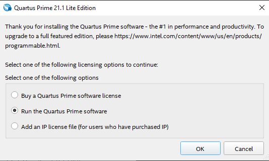
Wait until the installation is finished and then voila you've installed Quartus Prime. To run it just choose to run the Quartus Prime software.
Quartus Prime Synthesis Tutorial
1.3 Quartus Prime Tutorial
For this tutorial, we will use this code for reference :
LIBRARY IEEE;
USE IEEE.STD_LOGIC_1164.ALL;

ENTITY AND_GATE IS
    PORT (
        A : IN  STD_LOGIC;
        B : IN  STD_LOGIC;
        Y : OUT STD_LOGIC
    );
END AND_GATE;

ARCHITECTURE Behavioral OF AND_GATE IS
BEGIN
    Y <= A AND B;
END Behavioral;
1.3.1 Creating a New Quartus Prime Project
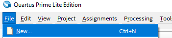
Create a new project by clicking new on file tab
Select New Quartus Prime Project

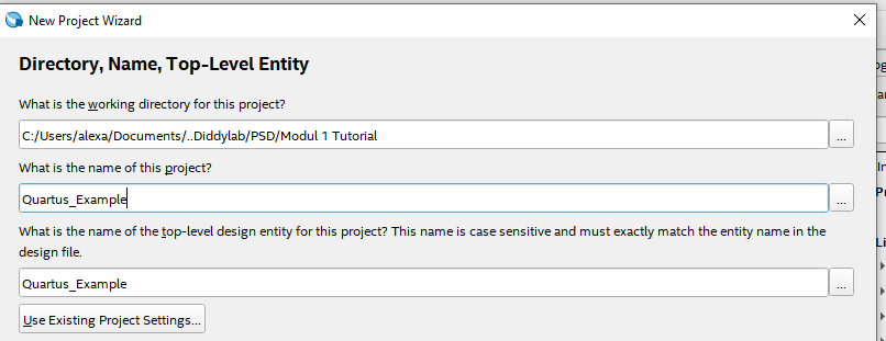
Select the directory where you want the project to be saved and also give the project a name and name your Top-Level Entity
NOTE : Remember to name your Top-Level Entity into the same name as your Top-Level entity on your .vhdl
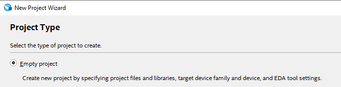
Choose empty project
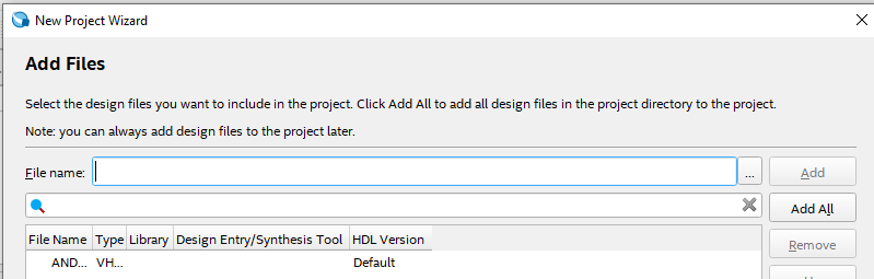
Add your .vhdl/.vhd file into the project
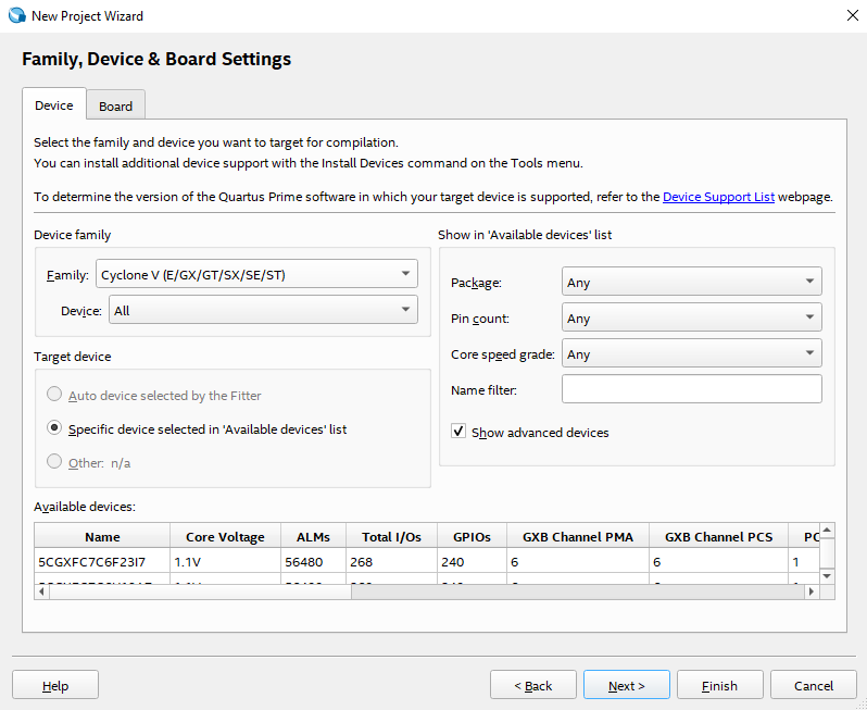
Just select the default setting and proceed to finish
1.3.2 Synthesis Tutorial
Run the "Start Compilation" button on top bar

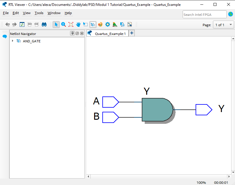
Wait until the startup is finish and then go into Tools -> Netlist Viewers -> RTL Viewer
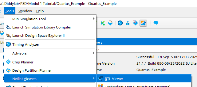
You may see your VHDL schematic
ModelSim Installation Tutorial
ModelSim Simulation Tutorial
Module 2 - Dataflow Style
1. Introduction to VHDL
1.1 What is VHDL
VHDL is an acronym for VHSIC HDL or, more completely, Very High-Speed Integrated Circuit Hardware Description Language. VHDL is a language used to describe hardware, so its writing style cannot be equated with high/low-level programming languages. A VHDL model or program can be translated into an actual digital circuit quickly with the help of software and, of course, according to specific needs; this process is known as synthesis. The resulting circuit can also be tested using VHDL to ensure it works according to the user's requirements. Before proceeding to the main material, readers are reminded to understand the concepts of Basic Digital Circuits (DSD) for ease in describing and designing hardware.
1.2 VHDL Syntax
Because VHDL is a language used to describe hardware, in addition to the correct output, tidy program writing is also needed to make it easier to understand. The following are VHDL writing conventions that need to be observed:
-
Case Sensitivity : VHDL is not case-sensitive, meaning that both uppercase and lowercase letters are recognized as the same object.
-
White Space : VHDL is not sensitive to white space, meaning that creating space using either a tab or a space bar has the same meaning.
-
Comments : Like programming languages in general, VHDL also has comments, which are made by using the
--sign. -
Parentheses : In VHDL, there are open and close parentheses
()which are used for precedence, giving a higher priority to the statement within them. -
VHDL Statements : Statements in VHDL always end with a
;or semi-colon. -
If, case, and loop Statements
-
Every
ifstatement is followed by athencomponent. -
Every
ifstatement ends withend if;. -
Else ifin VHDL is written aselsif. -
Every
casestatement ends withend case;. -
Every
loopstatement is terminated withend loop;.
-
-
Identifiers/Variables : Identifiers or variables in VHDL can use a combination of letters (A-Z and a-z) and numbers (0-9), must not end with an
_, and can have an unlimited length. It is important to name variables according to their function so they are easy to understand.
1.3 VHDL Operator
Operators in VHDL are grouped into 7 types: logical, relational, shift, adding, sign, multiplying, and others. The order of this list also describes the precedence of the operators. The following is a complete description of these operators:
- Logical
| Operator Type | ||||||
| Logical | and | or | nand | nor | xor | xnor |
- Relational
| Operator | Name | Explanation |
A = B |
equivalence | is A equivalent to B? |
A /= B |
non-equivalence | is A not equivalent to B? |
A < B |
less than | is A less than B? |
A <= B |
less than or equal | is A less than or equal to B? |
A > B |
greater than | is A greater than B? |
A >= B |
greater than or equal | is A greater than or equal to B? |
- Shift
| Operator | Name | Example | Result | |
| logical | sll | shift left logical | result <= "10010101" sll 2 | "01010100" |
| srl | shift right logical | result <= "10010101" srl 3 | "00010010" | |
| arithmetic | sla | shift left arithmetic | result <= "10010101" sla 3 | "10101111" |
| sra | shift right arithmetic | result <= "10010101" sra 2 | "11100101" | |
| rotate | rol | rotate left | result <= "10100011" rol 2 | "10001110" |
| ror | rotate right | result <= "10100011" ror 2 | "11101000" |
- Arithmetic
| Operator | Name | Comment | |
| adding | + | addition | |
| - | subtraction | ||
| & | concatenation |
can operate only on specific types
|
|
| sign | + | identity | unary operator |
| - | negation | unary operator | |
| multiplying | * | multiplication | |
| / | division |
often limited to powers of two
|
|
| mod | modulus |
can operate only on specific types
|
|
| rem | remainder |
can operate only on specific types
|
|
| miscellaneous | ** | exponentiation |
often limited to powers of two
|
| abs | absolute value |
1.4 Design Units
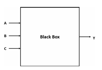
There are two important parts when designing a digital circuit using VHDL: "entity" and "architecture." These two units form a hierarchical design consisting of a black box and the components within it.
-
Entity : The entity is the first part of a VHDL design. It is the highest-level specification of a component or module in the design. In the entity, we define the component's external interface, including its inputs and outputs. The entity is the "black box" that describes what the component does and how it is accessed from the outside. The entity also defines the name of the component and the data types used.
library IEEE;
use IEEE.STD_LOGIC_1164.ALL;

-- The ENTITY describes the "black box" interface.
-- It defines the input and output ports.
entity Logic_Circuit is
    port (
        A, B, C : in  STD_LOGIC;  -- The three input pins
        Y       : out STD_LOGIC   -- The single output pin
    );
end Logic_Circuit;
-
Architecture : The architecture is the second part of a VHDL design. This section describes how the component works internally, including how the signals defined in the entity are processed and connected within that component.
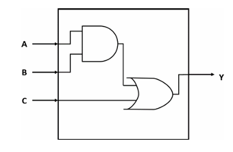
-- The ARCHITECTURE describes the internal logic.
-- It explains HOW the inputs are used to create the output.
architecture Dataflow of Logic_Circuit is
begin
    -- This single line of code represents the AND gate followed by the OR gate.
    Y <= (A and B) or C;
end Dataflow;
1.5 Data Objects
In VHDL, there are 4 types of Data Objects: signals, variables, constants, and files. The way to declare a data object for all types is more or less the same, as follows:
| VHDL data object | Declaration form |
| Signal | signal sig_name : sig_type:=initial_value; |
| Variable | variable var_name : var_type:=initial_value; |
| Constant | constant const_name : const_type:=initial_value; |
1.5.1 VHDL Signals
A signal in VHDL is the primary way to model a physical wire or connection in a hardware design. Declared within an architecture, its main purpose is to communicate data between different concurrent components, such as processes or logic gates. A signal is assigned a value using the <= operator, and this assignment is not immediate. it is scheduled to occur at a specific future time, which accurately reflects the signal propagation delay found in real-world circuits. This delayed behavior is essential for correctly modeling how different parts of a hardware design interact with each other. Signals is also only Declared in the declarative part of an architecture or package. There are two ways to declare signals :
Port Signal
A port signal is declared in the entity section of a VHDL design and represents an external connection. Its purpose is to define how the module sends and receives data from the outside world. Think of ports as the plugs and sockets on an appliance—they are the only way to interact with what's inside. You must specify a direction (or mode) for each port, such as in, out, inout, or buffer.
-- Port signals are declared inside the ENTITY
entity D_Flip_Flop is
    port (
        d, clk, rst : in  STD_LOGIC;  -- Input ports
        q           : out STD_LOGIC   -- Output port
    );
end D_Flip_Flop;

architecture Behavioral of D_Flip_Flop is
-- ... logic using the ports ...
end Behavioral;
Intermediate Signal
An intermediate signal is declared in the declarative part of the architecture and acts as an internal wire within your design. It is not visible from outside the module. Intermediate signals are essential for connecting different internal processes or concurrent statements, breaking down complex logic into simpler steps, or holding a value that needs to be used in multiple places within the architecture.
entity Complex_Gate is
    port (
        a, b, c, d : in  STD_LOGIC;
        y          : out STD_LOGIC
    );
end Complex_Gate;

-- Intermediate signal is declared inside the ARCHITECTURE
architecture Dataflow of Complex_Gate is
    -- This signal is an internal "wire" to hold a temporary result
    signal and_result_1 : STD_LOGIC;
begin
    -- The intermediate signal connects the output of the first AND gate
    -- to the input of the OR gate.
    and_result_1 <= a and b;
    y <= and_result_1 or (c and d);
end Dataflow;
1.5.2 VHDL Variables
A variable acts as temporary, local storage for calculations and does not represent a physical wire. It can only be declared and used inside a sequential block, such as a process (this will be explained more in module 3 : Behavioral Style) . The key distinction of a variable is its immediate update behavior. when a value is assigned using the := operator, the variable changes instantly and can be used in the very next line of code with its new value. This makes variables ideal for complex, multi-step algorithms where you need to store intermediate results without the delay and hardware overhead associated with a signal. Variables is also only Declared only inside a process, function, or procedure. It cannot be used to connect different processes.
library IEEE;
use IEEE.STD_LOGIC_1164.ALL;

-- Entity defines the inputs and outputs
entity Bit_Counter is
    port (
        data_in  : in  STD_LOGIC_VECTOR(7 downto 0); -- 8-bit input bus
        count_out: out INTEGER range 0 to 8          -- The final count
    );
end Bit_Counter;

-- Architecture shows the internal logic
architecture Behavioral of Bit_Counter is
begin
    -- A process is needed to use a variable
    count_process: process(data_in)
        -- 1. The variable is declared here, inside the process.
        -- It is initialized to 0 every time the process runs.
        variable bit_count : INTEGER := 0;
    begin
        -- Loop through each bit of the input signal
        for i in data_in'range loop
            if data_in(i) = '1' then
                -- 2. The variable is updated IMMEDIATELY.
                bit_count := bit_count + 1;
            end if;
        end loop;

        -- 3. The final result is assigned to the output signal.
        count_out <= bit_count;

    end process count_process;
end Behavioral;
1.5.3 VHDL Constant
A constant in VHDL is a data object that holds a fixed value which cannot be changed after it is declared using the constant NAME : TYPE := VALUE; syntax. Its primary purpose is to improve code readability and maintainability by assigning a descriptive name to a value, like using DATA_WIDTH instead of the number 8. This practice makes a design much easier to update, as changing the constant's value in its single declaration will automatically apply that change everywhere it's used, effectively acting like a labeled, unchangeable setting for your entire project. Constant can be declared in various places like a package, entity, architecture, or process.
-- First, define the constants in a package
package My_Design_Package is
    constant DATA_WIDTH : integer := 8;
    constant CLK_FREQ_HZ: integer := 50_000_000; -- 50 MHz
end package My_Design_Package;

-- Then, use the package in your design
library IEEE;
use IEEE.STD_LOGIC_1164.ALL;
use work.My_Design_Package.all; -- Makes our constants visible

entity My_Register_File is
    port (
        clk      : in  std_logic;
        data_in  : in  std_logic_vector(DATA_WIDTH - 1 downto 0); -- Uses the constant
        data_out : out std_logic_vector(DATA_WIDTH - 1 downto 0)  -- Uses the constant
    );
end My_Register_File;
1.5.5 Standard Data Types
In VHDL (VHSIC Hardware Description Language), there are various data types used to define the properties and types of variables, signals, and other objects in a hardware design. Here are some common data types in VHDL:
-
Signed : This data type is used to represent integers with a sign (signed integer). It is suitable for representing negative and positive numbers in hardware design.
-- Declaration
signal setpoint_signed    : SIGNED(7 downto 0);
signal feedback_signed    : SIGNED(7 downto 0);
signal error_value_signed : SIGNED(7 downto 0);

--  Usage Example: Calculate the difference between two signed values
error_value_signed <= setpoint_signed - feedback_signed;-
Unsigned : This data type is similar to "Signed," but it is only used to represent non-negative integers (unsigned integers).
-- Declaration
signal program_counter : UNSIGNED(15 downto 0);

-- Usage Example: Increment the counter in a clocked process
if rising_edge(clk) then
    program_counter <= program_counter + 1;
end if;-
STD_LOGIC : This data type is used to represent a single logic signal that can have the values '0', '1', 'Z' (high impedance), 'U' (uninitialized), 'X' (don't care), 'W' (weak), or 'L' (weak low).
-- Declaration
signal clk   : STD_LOGIC;
signal rst   : STD_LOGIC;
signal q_out : STD_LOGIC;

-- Usage Example: Using a reset signal to clear a register
if rst = '1' then
    q_out <= '0';
elsif rising_edge(clk) then
    -- ... other logic ...
end if;-
STD_LOGIC_VECTOR : This is a data type used to represent a vector of STD_LOGIC signals. You can use this type to represent a bus or a collection of logic signals in a hardware design (multiple bits).
-- Declaration
signal control_register : STD_LOGIC_VECTOR(7 downto 0);

-- Usage Example: Assigning a hexadecimal value to a control register
control_register <= x"A5"; -- Assigns the bit pattern "10100101"-
Integer : This data type is used to represent whole numbers, positive or negative. It is often used for counting and managing numerical values in a design.
-- Usage within a process
process(clk)
    -- Declaration (variable declared inside a process)
    variable i : INTEGER;
begin
    -- Usage Example: Controlling a loop a specific number of times
    for i in 0 to 15 loop
        -- ... perform an operation ...
    end loop;
end process;-
Boolean : This data type has two values, "True" or "False." It is used for conditioning and logical expressions.
-- Declaration
signal fifo_is_not_empty : BOOLEAN;
signal read_enable       : STD_LOGIC;

-- Usage Example: Using a boolean flag to control an operation
if fifo_is_not_empty = True then
    read_enable <= '1';
else
    read_enable <= '0';
end if;
1.6 VHDL Architecture Models
In VHDL, there are several approaches to explaining or describing an architecture. Hardware can be described using these styles or models according to its needs and complexity. These approaches are divided into three types:
-
Data-flow style : The data-flow approach describes a circuit by showing the relationship between the inputs and outputs of the components in the VHDL language. Concurrent signal assignment, conditional signal assignment, and selected signal assignment are the statements used in the data-flow style.
-
Behavioral style : The behavioral style approach doesn't describe how the circuit is implemented when synthesized. Instead, the behavioral style models how the circuit's output reacts to its inputs. The main component of the behavioral style is the process statement.
-
Structural style : The structural style approach is essentially a method that supports the interconnection of black boxes or entities. This style enables modular design, allowing you to connect previously separate components into a single circuit or entity. The structural style is commonly used when a circuit becomes increasingly complex, as it simplifies the description process.
2. Dataflow Style in VHDL
2.1 What is Dataflow Style
The Dataflow style is built on concurrency because the central idea is to model the system as a set of concurrent operations on signals, which directly reflects the physical reality of hardware. In any integrated circuit, all components are active and processing data in parallel; they don't execute in a step-by-step sequence. To accurately describe this, VHDL uses concurrent statements as the foundation. This approach ensures that the model's behavior matches the hardware's true, simultaneous nature, where multiple data transformations happen at the same time.
This is why the Dataflow style describes a circuit by focusing on the flow of data and the transformations applied to it, rather than specifying the exact gate-level structure. Each concurrent statement you write whether it's a simple logical operation or a conditional assignment defines one of these parallel transformations. This method allows you to build a functional description of the circuit by defining the paths and changes that signals undergo. By focusing on this "flow," you let the synthesis tool determine the best gate-level implementation, making it an intuitive and powerful way to translate a high-level circuit diagram into code.
2.2 Concurrent Statement
In general, digital circuits are concurrent in nature (working in parallel or simultaneously). A change in the output of a concurrent circuit is directly influenced by a change in an input. Therefore, VHDL also adopts the concept of concurrency when processing the inputs and outputs of a circuit. A program in VHDL cannot be equated to software programming where instructions are executed sequentially. Instructions in VHDL are executed directly and simultaneously. However, with certain techniques, VHDL can also describe sequential circuits whose processes are executed in order.
A concurrent statement is a method used to describe the parallel operation of hardware in VHDL. There are four ways to describe a concurrent statement:
-
Concurrent signal assignment : This is the most common method used to describe a concurrent statement. The output of the circuit can change at any time when one of its inputs changes. Example description of a 3-input NAND and AND gate using concurrent signal assignment:
library IEEE;
use IEEE.STD_LOGIC_1164.ALL;

-- Entity defines the inputs and outputs (the "black box")
entity Logic_Gates is
    port (
        a, b, c : in  STD_LOGIC;          -- Three inputs
        y_and   : out STD_LOGIC;          -- Output for the AND gate
        y_nand  : out STD_LOGIC           -- Output for the NAND gate
    );
end Logic_Gates;

-- Architecture describes what happens inside the box
architecture Behavioral of Logic_Gates is
begin
    -- These two statements are CONCURRENT. They happen at the same time.
    y_and  <= a and b and c;
    y_nand <= a nand b and c;

end Behavioral;-
Conditional signal assignment : This method is used to describe a statement that has a single target signal but has more than one condition to evaluate. Example description of a 2-to-1 Mux using conditional signal assignment:
library IEEE;
use IEEE.STD_LOGIC_1164.ALL;

-- Entity for a 2-to-1 Multiplexer
entity Mux_2_to_1_Conditional is
    port (
        i0, i1 : in  STD_LOGIC;  -- The two data inputs
        sel    : in  STD_LOGIC;  -- The select line
        y      : out STD_LOGIC   -- The single output
    );
end Mux_2_to_1_Conditional;

-- Architecture using the "when/else" concurrent statement
architecture Behavioral of Mux_2_to_1_Conditional is
begin
    -- The output 'y' gets the value of 'i0' WHEN 'sel' is '0',
    -- ELSE it gets the value of 'i1'.
    y <= i0 when sel = '0' else i1;

end Behavioral;-
Selected signal assignment : This method differs from the conditional signal assignment method. In a selected signal assignment, the target is based on the evaluation of an expression. Example description of a 2-to-1 Mux with selected signal assignment:
library IEEE;
use IEEE.STD_LOGIC_1164.ALL;

-- Entity for a 2-to-1 Multiplexer
entity Mux_2_to_1_Selected is
    port (
        i0, i1 : in  STD_LOGIC;  -- The two data inputs
        sel    : in  STD_LOGIC;  -- The select line
        y      : out STD_LOGIC   -- The single output
    );
end Mux_2_to_1_Selected;

-- Architecture using the "with/select" concurrent statement
architecture Behavioral of Mux_2_to_1_Selected is
begin
    -- WITH the value of 'sel', SELECT the output 'y'
    with sel select
        y <= i0 when '0',       -- When sel is '0', y gets i0
             i1 when '1',       -- When sel is '1', y gets i1
             'X' when others;  -- For any other value (like 'U' or 'Z'), output 'X' (unknown)

end Behavioral;-
Process Statement : A method that can be used to execute many instructions sequentially. This section will be discussed in more detail in module 3 regarding Behavorial Style.
Module 3 - Behavioural Style
A behavioral style in VHDL describes a digital system by specifying its functionality using high-level algorithms and sequential statements without detailing the underlying hardware structure.
Understanding Behavioral Style
One of the three architecture models is the behavioral style. Unlike the data-flow style, a VHDL program written in behavioral style does not need to describe how the circuit will be implemented when synthesized. Instead, the behavioral style describes how the circuit’s output will react to the inputs given to the circuit. The core of writing a program using the behavioral style is the process statement.
Using behavioral style in VHDL is like writing a recipe. You don’t explain how the kitchen is built or how the oven is wired (the hardware implementation); instead, you describe the steps the cook should follow and how the dish will turn out depending on the ingredients (the inputs). The process statement is like the main set of instructions in the recipe that guides the entire cooking process.

Process Statement
A process statement is a concurrent command that consists of a label, sensitivity list, declaration area, begin–end (body) area, and sequential statements. An example of a process statement description in VHDL is:
process (<Sensitivity List>)
  -- Variable declaration area
begin
  -- VHDL statement block here
end process;
The difference between a concurrent signal assignment statement and a process statement lies in the sequential statements. The syntax or statements inside the begin–end (body) section are executed sequentially, line by line, just like in general programming. The process label itself is simply a self-descriptive naming form to help us recognize which process is being executed in that section, so the naming can be changed or even omitted.
In a concurrent statement, every time a change occurs in the input, the output is re-evaluated. In a behavioral style model using a process statement, whenever a change occurs in a signal listed in the sensitivity list of the process, all the sequential statements within the process body are re-evaluated.
Since a process statement is itself a concurrent statement, if there are two processes in the architecture body, the execution of both processes will be carried out concurrently.
Sequential Statement
In a process, the execution of sequential statements will be initiated when there is a change in the signals listed in the sensitivity list. In general, the execution of statements in the process body will be carried out continuously until the end of the process sequentially. There are two types of sequential statements that will be discussed in this module:
● If statement
The if statement is used to create a branch in the execution flow of sequential statements. In VHDL, the if statement can only be used inside the process body. Example of a NAND gate with if statement:
library ieee;
use ieee.std_logic_1164.all;

entity nand_gate is
    port(
        A, B : IN STD_LOGIC;
        Y    : OUT STD_LOGIC
    );
end nand_gate;

architecture behavioral of nand_gate is
begin
    nand_proc : process (A, B) is
    begin
        if (A = '1' AND B = '1') then
            Y <= '0';
        else
            Y <= '1';
        end if;
    end process nand_proc;
end behavioral;
● Case statement
The case statement works in a way similar to the previous if statement. The difference is that the case statement will be more efficient to use when there are many variations of values. Example of a NAND gate using case statement:
library ieee;
use ieee.std_logic_1164.all;

entity nand_gate is
    port(
        A, B : IN STD_LOGIC;
        Y    : OUT STD_LOGIC
    );
end nand_gate;

architecture behavioral of nand_gate is
begin
    AB <= A & B;  -- combining signals A and B

    nand_proc : process (A, B) is
    begin
        case (AB) is
            when "11"    => Y <= '0';
            when others  => Y <= '1';
        end case;
    end process nand_proc;
end behavioral;
When using behavioral style, nested sequential statements are common and often used. This is also what makes behavioral style more powerful than data-flow style. However, even though behavioral style statements are used like programming in general, it should be noted that VHDL is a hardware description language, not a programming language. Also, try to always keep the process statement in the description you create as simple as possible to make hardware design easier when the circuit becomes more complex.
Wait Statements
Wait Statements
Wait statements are used to make a process wait for a certain condition, signal/variable, or a specific time interval. The following wait statements are used:
● Wait until [condition] and wait on [signal]wait until [condition] will block the process while checking whether a condition is true or false. The process will remain blocked until the condition being checked becomes true. Meanwhile, wait on [signal] will wait until there is a change in the specified signal. The syntax of wait until and wait on can be synthesized.
process is
begin
    signal1 <= '1';
    signal2 <= '0';

    wait until rst <= '1';

    signal1 <= '0';
    signal2 <= '1';

    wait on clk;
end process;
● Wait for [time period]wait for [time period] will block the process for the specified time period. The syntax of wait for cannot be synthesized but can be simulated in the waveform using ModelSim. Therefore, wait for is commonly used for a testbench, which will be studied in the next module.
process is
begin
    signal1 <= '1';
    signal2 <= '0';

    wait for 50 ps;

    signal1 <= '0';
    signal2 <= '1';

    wait for 100 ps;
end process;Report Statements
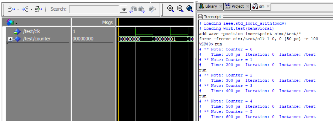
In VHDL, the report statement is used to generate text messages during simulation. This statement is useful for providing information about the status or certain values during simulation. The generated report will appear in the transcript to help with debugging.
‘Image Attribute
In VHDL, the 'image attribute is used to convert a certain data type into a string data type. This attribute is useful when you want to combine or display values of different data types in the form of a string. In a report statement, this attribute is used so that variables/signals can be printed to the transcript, which only accepts strings.
Here is an example of a report statement that also uses the 'image attribute:
LIBRARY IEEE;
USE IEEE.STD_LOGIC_1164.ALL;
USE IEEE.STD_LOGIC_ARITH.ALL;

ENTITY test IS
PORT (
    clk : IN STD_LOGIC
);
END test;

ARCHITECTURE Behavioral OF test IS
    SIGNAL counter : UNSIGNED(7 DOWNTO 0);
BEGIN
    PROCESS
    BEGIN
        WAIT FOR 50 ps;
        LOOP
            WAIT UNTIL rising_edge(clk);
            REPORT "Counter = " & INTEGER'image(conv_integer(counter));
            counter <= counter + 1;
        END LOOP;
    END PROCESS;
END Behavioral;
Example simulation:
Module 4 - Testbench
1. Understanding Testbench in VHDL
A VHDL testbench is a non-synthesizable VHDL entity used to simulate and verify the functionality of another VHDL entity, often referred to as the Unit Under Test (UUT). Think of it as a virtual lab environment where you can apply a sequence of inputs (stimulus) to your design and observe its behavior and outputs over time. Since the testbench itself is not meant to be turned into a physical chip, it can use more abstract and powerful VHDL constructs that are not available for synthesizable hardware descriptions.
A testbench has many uses, including:
- Simplifying and speeding up the entity testing process because inputs do not need to be manually entered one by one through a simulation tool.
- Allowing the entity's output to be compared against predetermined values to verify its correctness.
- Enabling the test results to be saved into files, such as a .csv file, so they can be used by other software like Python, Excel, or MATLAB for further analysis.
2. Components of a Testbench
2.1 Entity Declaration
The testbench entity is declared without any ports. It's a self-contained module because it doesn't connect to any higher-level design; it is the top-level entity for the simulation.
entity project_tb is
    -- Empty because testbench doesn't have any port
end project_tb
2.2 Architecture Declaration
2.2.1 UUT Component Declaration
Inside the architecture, we first declare the entity we want to test (the UUT) as a component. The component declaration must match the entity declaration of the UUT.
For example, if we have a UUT with these entity declaration:
entity earth_destroyer is
    Port (
        clk, rst    : IN STD_LOGIC;
        input       : IN STD_LOGIC VECTOR(7 downto 0);
        mode        : IN STD_LOGIC_VECTOR(3 downto 0);
        output      : OUT STD_LOGIC_VECTOR(7 downto 0)
    );
end earth_destroyer;
The UUT component declaration for that entity will be:
component earth_destroyer is
    Port (
        clk, rst    : IN STD_LOGIC;
        input       : IN STD_LOGIC VECTOR(7 downto 0);
        mode        : IN STD_LOGIC_VECTOR(3 downto 0);
        output      : OUT STD_LOGIC_VECTOR(7 downto 0)
    );
end component;
As you can see, component declaration is almost the exact same as entity declaration. Just make sure you change entity to component and use end component instead of end <entity name>, and you're good to go.
2.2.2 Signals Declaration
We must declare internal signals within the testbench architecture. You should at least declare all the signals that corresponds to the entity input/output ports. These signals will be connected to the ports of the UUT to drive its inputs and monitor its outputs.
For example, if we have earth_destroyer entity as in Part 2.2.1, we should declare these signals:
signal clk_tb    : STD_LOGIC := '0';
signal rst_tb    : STD_LOGIC;
signal input_tb  : STD_LOGIC VECTOR(7 downto 0);
signal mode_tb   : STD_LOGIC_VECTOR(3 downto 0);
signal output_tb : STD_LOGIC_VECTOR(7 downto 0);
The name of the signal doesn't really matter, as long as its data type match the port it corresponds to.
2.3 Port Map
In VHDL, a port map is part of the component instantiation within an architecture that maps the input and output ports of an entity to local signals. By using port map, we can connect a testbench to the entity being tested, allowing inputs to be driven and outputs to be observed through the testbench.
The general syntax of port map in a testbench is:
UUT : entity_name port map (entity_port_name => local_signal_name);
For example, if we want to instantiate the component as in Part 2.2, we can write it like this:
UUT : earth_destroyer port map (
    clk    => clk_tb,
    rst    => rst_tb,
    input  => input_tb,
    mode   => mode_tb,
    output => output_tb
);
3. Testbench Architecture Models
3.1 Testbench for Combinational Circuit
There are three architectural models for changing the value of inputs in a testbench. For example, if we want to make a testbench for a half adder entity below, we could use three methods:
library IEEE;
use IEEE.STD_LOGIC_1164.all;

entity half_adder is
    Port (
        a, b       : in STD_LOGIC;
        sum, carry : out STD_LOGIC
    );
end half_adder;

architecture arch of half_adder is
begin

    sum <= a xor b;
    carry <= a and b;

end arch;
3.1.1 Simple Testbench
This method is very similar to the dataflow style of VHDL programming. Values are directly assigned to input signals using the <= symbol. The difference is that each value assignment is separated by the after keyword, which indicates that the value will change after the testbench has run for the specified amount of time. For example, '1' after 60 ns means the value of the signal will change from '0' to '1' after the simulation has run for 60 ns from the very beginning.
library IEEE;
use IEEE.STD_LOGIC_1164.all;

entity half_adder_tb is
end half_adder_tb;

architecture tb of half_adder_tb is

    -- component declaration for half_adder
    component half_adder is
        Port (
            a, b       : in STD_LOGIC;
            sum, carry : out STD_LOGIC
        );
    end component;

    -- signal declaration for input/output stimulus
    signal a, b       : STD_LOGIC;    -- Input
    signal sum, carry : STD_LOGIC;    -- Output

begin
    -- component instantiation to connect tb to entity
    UUT: half_adder port map (
        a => a,
        b => b,
        sum => sum,
        carry => carry
    );

    -- input assignment (simple testbench)
    a <= '0', '1' after 20 ns, '0' after 40 ns, '1' after 60 ns;
    b <= '0', '1' after 40 ns;

end tb;
3.1.2 Testbench Using a process Statement
This method is similar to the behavioral style of VHDL programming, which uses a process statement. In this approach, every line of code inside the process is executed sequentially, one by one, much like in a typical programming language.
-- input assignment (process testbench)
tb1: process
    constant period    : time := 20 ns;
    begin
        a <= '0';
        b <= '0';
        wait for period;

        a <= '0';
        b <= '1';
        wait for period;

        a <= '1';
        b <= '0';
        wait for period;

        a <= '1';
        b <= '1';
        wait for period;

        wait; -- wait until the end of time
    end process;
3.1.3 Testbench Using a Look-up Table
This method is an extension of the process-based testbench. Instead of assigning each combination of values one by one, this method works by storing the combinations in a separate variable, called a look-up table (which can be a signal or a constant).
-- input assignment (look-up table testbench)
tb1: process
    constant period    : time := 20 ns;
    constant stream_a  : STD_LOGIC_VECTOR(0 to 3) := ('0', '1', '0', '1');
    constant stream_b  : STD_LOGIC_VECTOR(0 to 3) := ('0', '0', '1', '1');

    begin
        a <= stream_a(0);
        b <= stream_b(0);
        wait for period;

        a <= stream_a(1);
        b <= stream_b(1);
        wait for period;

        a <= stream_a(2);
        b <= stream_b(2);
        wait for period;

        a <= stream_a(3);
        b <= stream_b(3);
        wait for period;

        wait; -- wait until the end of time
    end process;
You can also use for loop for a more efficient implementation, but more of it will be covered in Module 6 and it's not recommended for this module.
3.2 Testbench for Sequential Circuit
A testbench for a sequential circuit is not much different from a testbench for a combinational circuit. The main difference is the need for several additional inputs, including a Clock and a Reset.
3.2.1 Clock Process
The clock is the heartbeat of a sequential circuit. In a testbench, the clock signal must be generated continuously throughout the simulation to drive the Unit Under Test (UUT). This is almost always done using a dedicated, independent process.
-- Inside of testbench architecture
    constant period    : time := 20 ns;    -- clock period
    signal clk         : STD_LOGIC;        -- clock signal

begin
    clk_generator : process
    begin
        clk <= '0';
        wait for period/2;
        clk <= '1';
        wait for period/2;
    end process;
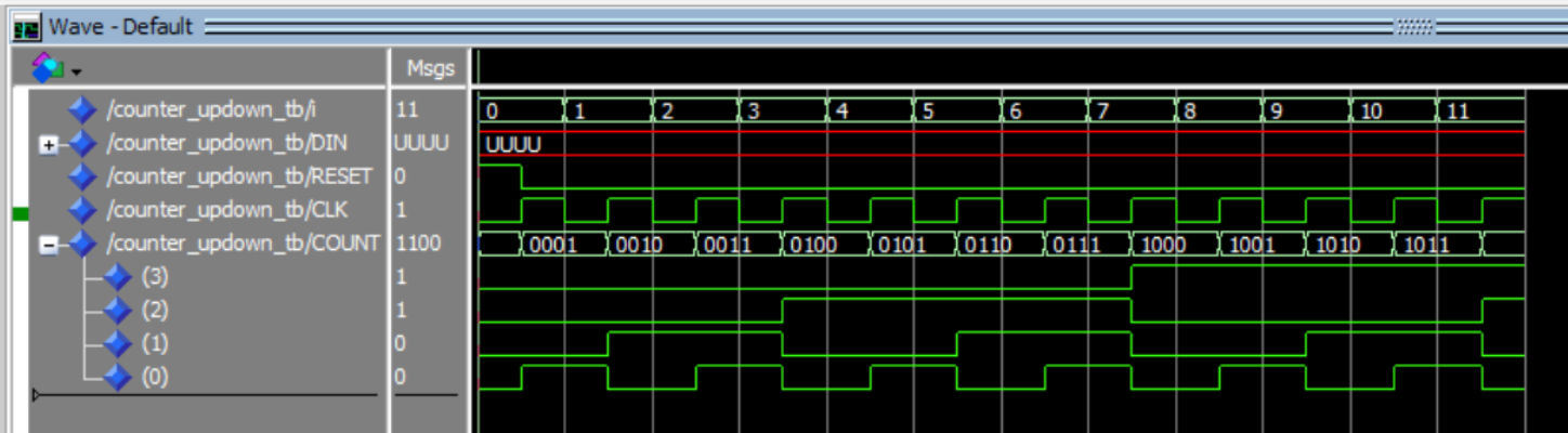
3.2.2 Example of Testbench for Sequential Circuit
For example, we want to make a testbench for this updown counter entity:
library IEEE;
use IEEE.std_logic_1164.all;
use IEEE.numeric_std.all;

entity counter_updown is
    Port (
        RESET, CLK, LD, UP : in std_logic;
        DIN                : in std_logic_vector (3 downto 0);
        COUNT              : out std_logic_vector (3 downto 0)
    );
end counter_updown;

architecture my_count of counter_updown is
    signal t_cnt : unsigned(3 downto 0); -- internal counter signal
begin
    process (CLK, RESET)
    begin
        if (RESET = '1') then
            t_cnt <= (others => '0'); -- clear
        elsif (rising_edge(CLK)) then
            if (LD = '1') then t_cnt <= unsigned(DIN); -- load
            else
                if (UP = '1') then t_cnt <= t_cnt + 1; -- incr
                else t_cnt <= t_cnt - 1; -- decr
                end if;
            end if;
        end if;
    end process;
    COUNT <= std_logic_vector(t_cnt);
end my_count;
In this case, the testbench combines the three architectural models that were previously explained. The Clock signal uses a process statement, while the Reset signal uses the simple assignment method. The other inputs are assigned directly in the declaration section because their values will not change.
Additionally, it is important to note the presence of the max_clk variable, which is used to limit the number of clock cycles run by the testbench. If the clock cycles are not limited, the testbench will continue to run indefinitely unless the program is stopped manually.
library ieee;
use ieee.std_logic_1164.all;
use ieee.numeric_std.all;

entity counter_updown_tb is
end counter_updown_tb;

architecture arch of counter_updown_tb is
    component counter_updown is
        Port (
            RESET, CLK, LD, UP : in std_logic;
            DIN                : in std_logic_vector (3 downto 0);
            COUNT              : out std_logic_vector (3 downto 0)
        );
    end component;

    constant period    : time := 20 ns;    -- clock period
    constant max_clk   : integer := 11;    -- maximum clock cycle
    signal cnt         : integer := 0;     -- clock cycle counter

    constant LD        : std_logic := '0';              -- input
    constant UP        : std_logic := '1';              -- input
    signal DIN         : std_logic_vector(3 downto 0);  -- input
    signal RESET       : std_logic;                     -- input
    signal CLK         : std_logic;                     -- input
    signal COUNT       : std_logic_vector(3 downto 0);  -- output

begin
    UUT : counter_updown port map (RESET, CLK, LD, UP, DIN, COUNT);

    -- reset = '1' at the first clock cycle, then change to '0'
    reset <= '1', '0' after period/2;

    CLK_generator : process
    begin
        CLK <= '0';
        wait for period/2;
        CLK <= '1';
        wait for period/2;

        if(cnt < max_clk) then cnt <= cnt + 1;
        else wait;
        end if;
    end process;
end arch;
Here is the simulation result of the testbench above:
4. Assert and Report Statement
4.1 Assert Statement
The assert statement is used for creating self-checking testbenches. It acts like an automated check that constantly monitors a condition. If the condition is false, it "asserts" a message, alerting us to a problem without requiring us to manually inspect the waveforms.
The full syntax of an assert statement is:
ASSERT condition REPORT "message" SEVERITY level;
ASSERT condition: This is the boolean expression that you expect to be true. For example,(actual_output = expected_output).REPORT "message": This is the message that gets printed to the simulator's console only if the condition is false. It's used to provide context about the failure.SEVERITY level: This is a crucial part of the statement that tells the simulator how to react to the failure.
For example, if we want to implement the assert statement in our testbench from section 3.1.2, we can implement it as below:
tb1: process
    constant period    : time := 20 ns;
    begin
        a <= '0';
        b <= '0';
        wait for period;

        assert ((sum = '0') and (carry = '0'))
        report "tes gagal pada testcase ke-1" severity error;

        a <= '0';
        b <= '1';
        wait for period;

        assert ((sum = '1') and (carry = '0'))
        report "tes gagal pada testcase ke-2" severity error;

        a <= '1';
        b <= '0';
        wait for period;

        assert ((sum = '1') and (carry = '0'))
        report "tes gagal pada testcase ke-3" severity error;

        a <= '1';
        b <= '1';
        wait for period;

        assert ((sum = '0') and (carry = '1'))
        report "tes gagal pada testcase ke-4" severity error;

        wait; -- wait until the end of time
    end process;
The following is the output produced by the testbench:

4.2 Severity Level
The severity level tells the simulator how serious the failed assertion is. There are four standard levels:
| Level | Description | Simulator Action |
|---|---|---|
NOTE |
Informational message. Used for debugging, tracing, or indicating progress. | Prints the message and continues simulation. |
WARNING |
Non-critical issue. Something is unexpected or out of spec, but the design might still function. | Prints a warning and continues simulation. Increments a warning counter. |
ERROR |
Functional failure. The design's output is incorrect. This is the standard for a failed test. | Prints an error and continues simulation. Increments an error counter. |
FAILURE |
Catastrophic/Fatal error. Something is fundamentally broken, making further simulation pointless. | Prints a failure message and immediately halts the simulation. |
Note that if we don't explicitly specify which severity level used in a report statement, it automatically defaults to note.
5. File I/O in VHDL
In VHDL, we can perform file handling using the TextIO library. This feature is very useful for documenting the results of a program that has been created. To use the TextIO library, we need to add it at the beginning of our program as follows:
use std.textio.all;
use ieee.std_logic_textio.all; -- For std_logic types
5.1 Read File
When repeatedly simulating a design, changing the value of each input one by one can be time-consuming and inefficient. Therefore, we can use a feature from the TextIO library that can read inputs from a file to be used in the design simulation.
Here is how to read input from a file in VHDL. First, we can define the file to be read within a process statement and open it in read_mode:
process
    -- Define the file and its open mode
    file text_file   : text open read_mode is "filename.txt";

    -- Variable to receive data from the file
    variable fileinp : integer;

    -- Line type variable to hold a row from the text file
    variable row     : line;

    -- Variale to store file reading status
    variable ok      : boolean
Then, we can read the file using the readline and read procedures from the TextIO library as follows:
begin
    while not endfile(text_file) loop --loop until the end of the text file
        readline(text_file, row); --reads the line from the file

        -- Skip empty lines or comments that start with '#'
        if row.all'length = 0 or row.all(1) = '#' then
            next;
        end if;

        -- Reads a variable from the line and puts it into fileinp
        read(row, fileinp, ok);

        assert ok
        report "Read 'sel' failed for line: " & row.all
        severity failure;  --report if the file read fails

        wait for delay; --delay for the read iteration
    end loop;
end process;
5.2 Write File
Besides reading a set of inputs to be used in a testbench, we can also use the TextIO library to save the results of our testbench to a file. This allows us to analyze the results without having to use a simulator like ModelSim or Vivado.
Here are the steps required to write the results of a testbench to a file. First, we can define the file to be created and open it in write_mode:
process
    -- Open "filename.txt" in write mode
    file text_file      : text open write_mode is "filename.txt";

    -- Line type variable to build a row for the text file
    variable row        : line;

    -- Variable holding the data to be written to the file
    variable data_write : integer;
Then, we can use the write and writeline procedures rom the TextIO library to write data to the file as follows:
begin
    -- writes data to the file, left-justified, 15 characters
    write(row, data_write, left, 15);

    writeline(text_file, row); -- writes the line to the file
end process;
Extra: Array in VHDL
6.1 Array
In VHDL, an array is a collection of elements that share the same data type. You can think of an array as a variable that holds many elements of the same type, and these elements are indexed to be accessed. The index can be a number or another indexable type, such as integer, natural, or std_logic_vector. Arrays can have one dimension (one-dimensional array) or more (two-dimensional, three-dimensional, and so on). Two-dimensional arrays are often used to represent tables or matrices.
6.2 Type
A type is a definition used to declare a new data type in VHDL. A type can be used to define complex data types, such as arrays or records, or as a type used to declare variables, ports, or signals. Types can also be used to describe the properties and structure of data.
VHDL has predefined data types, such as std_logic, std_logic_vector, integer, and others, but we can also create our own custom data types. Types that are predefined or embedded in VHDL libraries are called "built-in types," while types that we define ourselves are called "user-defined types."
Here is an example of using type and array to create a bank of 8-bit registers:
type RegisterArray is array (0 to 7) of std_logic_vector(7 downto 0);
signal registers : RegisterArray := (others => (others => '0'));
In the example above, we are defining a structure that could be used in an entity like a RegisterBank which has eight 8-bit registers. These registers are represented by the registers array, which has 8 elements, each with a length of 8 bits.
Module 5 - Structural Programming
1. Structural Programming in VHDL
1.1 Structural Style
Structural Style Programming is an approach in VHDL that allows designers to create digital circuits by using basic components connected to each other to form a more complex system. In this approach, a circuit is represented as a collection of entities linked in a specific way to achieve the desired function.
1.2 Port Mapping
Port mapping is the process of associating (mapping) the ports of a component (entity) in VHDL with the signals present in the architecture. This allows us to connect a defined entity to the actual circuit in the design.
Some important points:
- Entity Definition: An entity must be defined before port mapping.
- Port-Map List: A list that maps ports to signals.
- Port Mapping Order: The order must match the entity's port definition.
- Signal Declaration: Signals must be declared beforehand.
Port Mapping Example
-- Entity definition
entity AND2 is
  port (
    A, B: in std_logic;
    Y: out std_logic
  );
end entity;

-- Port mapping in architecture (this is actually the entity's behavior)
architecture RTL of AND2 is
begin
  Y <= A and B;
end architecture;

-- Using the entity with port mapping in a higher-level design
D1: AND2 port map (
  A => input_signal_A,
  B => input_signal_B,
  Y => output_signal
);
2. Generic Map
2.1 Generic Map Explanation
A generic map is the process of associating a generic value in an entity with a value in the architecture. Generics are parameters used to configure a component.
Some important points:
- Generic: A parameter to change the characteristics of an entity.
- Generic Map: Sets the value of the generic during instantiation.
- Default Value: Used if a value is not explicitly set.
2.2 Generic Map Example
entity Counter is
  generic (
    WIDTH: positive := 8;
    ENABLED: boolean := true
  );
  port (
    clk: in std_logic;
    reset: in std_logic;
    count: out std_logic_vector(WIDTH-1 downto 0)
  );
end entity;

architecture RTL of MyDesign is
  signal my_counter_output: std_logic_vector(7 downto 0);
begin
  my_counter_inst: Counter
    generic map (
      WIDTH => 8,
      ENABLED => true
    )
    port map (
      clk => system_clock,
      reset => reset_signal,
      count => my_counter_output
    );
end architecture;
3. VHDL Modularity
3.1 VHDL Modularity Explanation
Example: 4-bit Ripple Carry Adder using 4 Full Adders. A Ripple Carry Adder adds binary numbers with a chained carry.
3.1.1 Stage 1: Full Adder
entity Full_Adder is
  port (
    A, B, Cin: in std_logic;
    Sum, Cout: out std_logic
  );
end entity Full_Adder;

architecture RTL of Full_Adder is
begin
  Sum <= (A xor B) xor Cin;
  Cout <= (A and B) or ((A xor B) and Cin);
end architecture;
3.1.2 Stage 2: 4-bit Ripple Carry Adder
entity Four_Bit_RCA is
  port (
    A, B: in std_logic_vector(3 downto 0);
    Sum: out std_logic_vector(3 downto 0);
    Cout: out std_logic
  );
end entity Four_Bit_RCA;

architecture RTL of Four_Bit_RCA is
  signal Carry: std_logic_vector(3 downto 0);
begin
  FA0: Full_Adder port map (A(0), B(0), '0', Sum(0), Carry(0));
  FA1: Full_Adder port map (A(1), B(1), Carry(0), Sum(1), Carry(1));
  FA2: Full_Adder port map (A(2), B(2), Carry(1), Sum(2), Carry(2));
  FA3: Full_Adder port map (A(3), B(3), Carry(2), Sum(3), Cout);
end architecture;
3.1.3 Stage 3: Testbench
entity RCA_tb is
end entity RCA_tb;

architecture RTL of RCA_tb is
  signal A, B, Sum: std_logic_vector(3 downto 0);
  signal Cout: std_logic;
  signal Clock: std_logic := '0';
  constant Clock_Period: time := 10 ns;

  component Four_Bit_RCA
    port (
      A, B: in std_logic_vector(3 downto 0);
      Sum: out std_logic_vector(3 downto 0);
      Cout: out std_logic
    );
  end component;
begin
  Clock_Process: process
  begin
    while now < 1000 ns loop
      Clock <= not Clock;
      wait for Clock_Period / 2;
    end loop;
    wait;
  end process;

  A <= "1101";
  B <= "0011";

  RCA: Four_Bit_RCA port map (A, B, Sum, Cout);

  process
  begin
    wait until rising_edge(Clock);
    if Cout = '1' then
      report "The addition result is overflowing";
    end if;
    report "Addition result: " & to_string(Sum);
    wait;
  end process;
end architecture RTL; -- Corrected from Main_Architecture to RTL
4. Array and Type
4.1 Array and Type in VHDL
4.1.1 Array
An array is a collection of elements of the same data type. It can be one-dimensional or multi-dimensional.
4.1.2 Type
A type is a new data definition. It can be a built-in type (std_logic, integer) or a user-derived type.
4.2 Type and Array Example
type RegisterArray is array (0 to 7) of std_logic_vector(7 downto 0);
signal registers: RegisterArray := (others => (others => '0'));
Module 6 - Looping Construct
loop
Introduction to Looping Constructs
Introduction to Looping Constructs
Looping constructs are VHDL instructions that allow a program to repeat the same block of code, a process known as iteration (similar to C).
Loops in VHDL are divided into two main categories based on how they function and what they create.
1. Sequential Loops (Inside a process)
These loops are similar to those in traditional programming languages. They describe an algorithm or a sequence of operations that execute step-by-step.
- They can only be used inside a
process,function, orprocedure. - They are synthesized into hardware that performs an operation over multiple clock cycles or as a large block of combinational logic.
There are two main types of sequential loops:
-
forloop -> Repeats for a specific number of times. Use this when you know the exact number of iterations. -
whileloop -> Repeats as long as a certain condition istrue. Use this when the number of iterations is unknown.
2. Concurrent Loops (Outside a process)
This type of loop is unique to hardware description languages. It doesn't describe an algorithm but instead describes the replication of hardware structures. It acts like copy and pasting ICs on a breadboard.

(well, that's the gist of it)
-
It creates multiple instances of concurrent statements (like component instantiations).
-
It is only used outside of a
process, in the main architectural body. -
The main type is the
for-generateloop.
For Loop
For Loop
The for loop is the most common type of sequential loop in VHDL. It is used to repeat a block of code a specific, pre-determined number of times. This makes it ideal for tasks where you know exactly how many iterations you need, such as processing the bits of a vector.
Syntax
The basic structure of a for loop is:
loop_label: for <index_variable> in <range> loop
    -- code code code...
end loop loop_label;
Example:
testloop: for i in 0 to 2 loop
    -- code cedo deco ... .. . .
end loop
loop_labelis the name of the loop (recommended!). It's not mandatory, but helps a lot in coding.<index_variable>is a temporary var that holds the value of the current iteration.<range>, the sequence of values the index will take. This is defined withtofor an ascending range (0 to 7) ordowntofor a descending range (7 downto 0).
Notes
When using a for loop, there are a few important rules to remember:
- The index variable (
i) is created automatically by the loop and does not need to be declared in the process. - You can read the value of
iwithin the loop, but you cannot manually assign a new value to it. - The loop index will always increment or decrement by one in each iteration. You cannot specify a different step value.
Example: Init Memory
The code below shows the for loop iterating through every address of the memory to write a '0' value to it, like setting a RAM's content to 0.
type t_memory is array(0 to 63) of std_logic_vector(7 downto 0);

-- Inside your architecture...
p_Memory_Reset: process (i_Clock, i_Reset)
    variable v_ram : t_memory;
begin
    if (i_Reset = '1') then
        -- Initialize all 64 locations of the RAM to zero.
        -- We use a label "RAM_INIT_LOOP" for clarity.
        RAM_INIT_LOOP: for i in v_ram'range loop
        -- RAM_INIT_LOOP: for i in 0 to 63 loop <- would work too. variable`range is more flexible
            v_ram(i) := (others => '0');
        end loop RAM_INIT_LOOP;

    elsif rising_edge(i_Clock) then
        -- ... normal memory operation code ...
    end if;
end process p_Memory_Reset;
This loop is much cleaner than writing 64 individual lines of code. It uses v_ram'range (variable'range) to automatically loop through the entire size of the array.
While Loop
While Loop
The while loop is used where the number of repetitions is not known from the start. A while loop continues to execute as long as a specified condition is true.
Syntax
The basic structure of a while loop is:
loop_label: while <condition> loop
    -- Going through...
    -- IMPORTANT: Must include logic to eventually make the condition false!
end loop loop_label;
<condition>is a boolean expression that is checked before each iteration. If it'strue, the loop body executes. If it'sfalse, the loop terminates.
Warning: Infinite Loops
A while loop can create an infinite loop. This occurs if the loop's condition never becomes false. Unlike in C, Java, Python etc. where infinite loops are harmless, VHDL shouldn't have these.
- In a simulation, an infinite loop will cause the simulator to hang and never finish.
- In synthesis, it can be interpreted as a feedback path that creates a latch, or the synthesizer might fail with an error.
To avoid this, ensure that the logic inside the loop will eventually cause the condition to become false.
Example: Finding the First '1'
In this example, we'll search a vector from left to right (from the most significant bit) to find the position of the first bit that is a '1'.
Notice that unlike a for loop, we must manually declare and update our index variable (i).
-- Inside a process...
p_Find_First_One: process(a_vector)
    -- We must declare our own index variable for a while loop
    variable i : integer := a_vector'left; -- Start at the leftmost bit
    variable i_position : integer := -1; -- -1 if no 1 is found
begin
    -- Reset variables for each run of the process
    i_position := -1;
    i := a_vector'left;

    FIRST_ONE: while (i >= a_vector'right) loop

        if a_vector(i) = '1' then
            i_position := i;
            exit FIRST_ONE; -- Quit if found
        end if;

        -- Manually decrement the index to check the next bit
        i := i - 1;

    end loop SEARCH_LOOP;

    -- Assign the result to a signal
    found_position_signal <= i_position;

end process p_Find_First_One;
In this code, the loop continues as long as i is within the vector's bounds. If a '1' is found, the exit statement terminates the loop early. If no '1' is found, the loop completes naturally when i goes out of bounds.
Loop Control - Next & Exit
Loop Control - Next & Exit
The two control statements, next and exit, allow you to skip an iteration or terminate the loop entirely, giving you more precise control over your sequential code.
These statements can be used in both for and while loops.
One, The next Statement
The next statement immediately stops the current loop iteration and jumps to the beginning of the next one. Any code that comes after the next statement within the loop body is skipped for that specific iteration (same thing as in C!).
The syntax can be written in two ways:
-- Form 1: Using an if-statement
if <condition> then
    next;
end if;

-- Form 2: Using the 'when' keyword
next when <condition>;
Example: Summing Only Odd Numbers
To skip even numbers, the next statement is perfect!
-- Inside a process...
variable sum : integer := 0;
...
SUM_ODD_LOOP: for i in 1 to 10 loop
    -- If the number is even, skip to the next iteration
    next when (i mod 2 = 0);

    -- This line is only reached for odd numbers
    sum := sum + i;
end loop SUM_ODD_LOOP;
-- At the end, sum will be 1+3+5+7+9 = 25
Two, The exit Statement
The exit statement terminates the loop entirely. As soon as exit is executed, the program moves to the line after end loop.
The syntax is similar to next:
-- Form 1: Using an if-statement
if <condition> then
    exit;
end if;

-- Form 2: Using the 'when' keyword
exit when <condition>;
Example: Finding a Value in Memory
Say, we want to search through a memory to find an address that holds a specific value. Once we find it, there is no reason to continue searching.
-- Inside a process...
constant SEARCH_VALUE : std_logic_vector(7 downto 0) := x"A5";
variable found_addr : integer := -1; -- Default value
...
SEARCH_MEM_LOOP: for i in ram'range loop
    -- If the value at the current address matches,
    -- store the address and exit the loop immediately.
    if ram(i) = SEARCH_VALUE then
        found_addr := i;
        exit SEARCH_MEM_LOOP;
    end if;
end loop SEARCH_MEM_LOOP;

-- The code goes on...
Using exit makes the search efficient. It prevents the loop from doing unnecessary work after the item has been found.
For-Generate Loop
The Concurrent 'for-generate' Loop
We now switch from sequential loops to a concurrent one.
The for-generate statement is not a loop that executes over time inside a process. Instead, it's a command that tells the synthesizer to create multiple copies of hardware structures.
It's good for repetitive structures like registers and chains of components. A key rule is that for-generate is used outside of a process, in the main architectural body.
Main Differentiators
- This loop is Concurrent, not Sequential. All the hardware instances created by the loop exist simultaneously and operate in parallel. The synthesizer "unrolls" the loop, creating all the copies before the design is even simulated or synthesized.
- This is most often used to create multiple instances of a
component, but can also be used for concurrent signal assignments or even entireprocessblocks.
Syntax
The basic structure of a for-generate statement is:
generate_label: for <identifier> in <range> generate
    -- Concurrent statements to be replicated go here...
    -- (e.g., component instantiations)
end generate generate_label;
- Label, identifier, and range, all follow the same rules as the other loops (
forandwhile).
Example: 4-Bit Adder
We start with a 1-bit full adder and use for-generate to create and connect four of them in a chain to make a 4-bit adder.
1. Replication Target First, we need the definition of the 1-bit full adder that we want to copy.
component full_adder is
    port (
        A, B, Cin  : in  std_logic;
        S, Cout    : out std_logic
    );
end component;
2. 4-Bit Adder Architecture
Next, we use for-generate to create four instances of the full_adder and wire them together.
entity four_bit_adder is
    port (
        A, B    : in  std_logic_vector(3 downto 0);
        Cin     : in  std_logic;
        S       : out std_logic_vector(3 downto 0);
        Cout    : out std_logic
    );
end entity;

architecture structural of four_bit_adder is
    -- Internal signal to wire the carry chain between the adders.
    -- It needs 5 bits to include the first Cin and final Cout.
    signal C : std_logic_vector(4 downto 0);
begin

    -- The first carry wire is connected to the adder's carry-in pin
    C(0) <= Cin;

    -- Generate the chain of 4 full adders
    ADDER_CHAIN: for i in 0 to 3 generate
        -- Create one instance of the full_adder in each "iteration"
        FA_INSTANCE: full_adder
            port map (
                A    => A(i),       -- Connect to the i-th bit of input A
                B    => B(i),       -- Connect to the i-th bit of input B
                Cin  => C(i),       -- The carry-in for this bit
                S    => S(i),       -- The sum output for this bit
                Cout => C(i+1)      -- The carry-out for this bit
            );
    end generate ADDER_CHAIN;

    -- The final carry-out of the chain is the adder's carry-out pin
    Cout <= C(4);

end architecture structural;
Physically (RTL wise), this is the exact same as copy-pasting the 4 adders manually. So, this approach is much cleaner and more organized.
When & Which
When & Which?
Comparison
| Feature | for Loop |
while Loop |
for-generate Statement |
|---|---|---|---|
| Execution | Sequential | Sequential | Concurrent |
| Usage Location | Inside a process |
Inside a process |
Outside a process |
| Iteration | Fixed number of times | Repeats while a condition is true |
Creates N physical copies |
| Purpose | Algorithmic tasks | Searching or Polling | Hardware Replication |
Quick Guide
-
Use a
forloop when...- You need to repeat an action a specific number of times.
- Iterating through all the bits of a vector, initializing every address in a memory.
-
Use a
whileloop when...- You need to repeat an action until a condition changes, and you don't know how long that will take.
- Searching for the first occurrence of a value, waiting for a status flag to be set in a testbench.
-
Use a
for-generatestatement when...- You need to create multiple, regular instances of hardware components or concurrent statements.
- Building an N-bit register from N flip-flops, creating a chain of adders, connecting several identical modules to a bus.
Remember, all loops have the same syntax rules, so you just need to remember the structure. Good luck! :+1:
Module 7 - Procedure, Function, and Impure Function
Procedure
In VHDL, a procedure is a type of language construct used to group several statements and specific tasks into a single block of code. Procedures help in organizing and simplifying the understanding of complex VHDL designs.
A procedure in VHDL is similar to a void function in languages like C. It performs a specific task but does not return a value. Instead, it may modify signals or variables passed to it as parameters, allowing designers to reuse code and improve readability.
Procedure Declaration
A procedure is defined using a procedure declaration. This declaration specifies the procedure name, any required parameters (if any), and the data type that is returned (if applicable). Below is an example of a procedure declaration in VHDL:
procedure Nama_Procedure(parameter1: tipe_data; parameter2: tipe_data) return tipe_data
  is
  begin
  -- Blok kode procedure
end Nama_Procedure;
Parameters in Procedure
A procedure can accept parameters as arguments. These parameters are used to pass data into the procedure so that it can be processed. The required parameters are defined in the procedure declaration and can be of different modes such as in, out, or inout, depending on whether the data is being read, written, or both.
Procedure Body (Code Block)
The body of a procedure is the section where the tasks to be performed by the procedure are written. Within this block, you can write statements to perform various operations such as calculations, condition checks, data manipulation, and more. This is where the logic of the procedure is implemented, similar to the body of a function in other programming languages.
Procedure Call
To use a procedure, it can be called from the main part of the design or from within another procedure. A procedure is invoked by providing arguments that match the parameters defined in its declaration. Below is an example of how a procedure is used in VHDL.
variable1 := Nama_Procedure(nilai_parameter1, nilai_parameter2);
Example Code
library ieee;
use ieee.std_logic_1164.all;
use ieee.numeric_std.all;

entity Procedure_Example is
  port(
    clk : in std_logic;         -- Clock input
    result_out : out integer    -- Output to observe the result
  );
end Procedure_Example;

architecture Behavioral of Procedure_Example is

  -- Signal declarations
  signal sigA : integer := 5;
  signal sigB : integer := 7;
  signal adder_result : integer;

  procedure adder(
    A, B : in integer;       -- Input parameters
    Hasil : out integer      -- Output parameter (will write to adder_result)
  ) is
  begin
    Hasil := A + B;
  end procedure;

begin

  process(clk)
  begin
    if rising_edge(clk) then
      adder(sigA, sigB, adder_result);  -- Call the procedure
    end if;
  end process;

  -- Output assignment
  result_out <= adder_result;

end Behavioral;
Function
In VHDL, a function is a subprogram used to perform calculations or data processing that returns a single value as a result. Functions in VHDL are similar to functions in traditional programming languages such as C or Java, where the main purpose is to compute a value based on the input arguments. Unlike procedures, functions must return exactly one value and cannot modify signals or variables outside the function directly. They are typically used for operations like arithmetic, logical computations, or data conversion.
Functions improve code readability, reusability, and modularity in complex VHDL designs.
Function Declaration
A function is defined using a function declaration. This declaration specifies:
- The function name
- Input parameters (if any)
- The return data type
Below is an example of a function declaration in VHDL:
function Function_Name(parameter1: data_type; parameter2: data_type) return return_type is
begin
  -- Function code block
  return value;
end Function_Name;
Parameters in Function
A function can accept input parameters only. These parameters are used to pass data into the function to be processed. Unlike procedures, functions cannot have out or inout parameters. All data returned from a function must be provided through the return statement.
Function Body (Code Block)
The body of a function contains the logic used to compute and return a value. This may include arithmetic operations, conditions, or other expressions. The function must include a return statement that provides the final result.
Function Call
A function is called by using its name and passing the required arguments. The returned value can be directly assigned to a signal or variable.
variable1 := Function_Name(input_value1, input_value2);
Example Code
library ieee;
use ieee.std_logic_1164.all;
use ieee.numeric_std.all;

entity Function_Example is
  port(
    clk : in std_logic;         -- Clock input
    result_out : out integer    -- Output to observe the result
  );
end Function_Example;

architecture Behavioral of Function_Example is

  -- Signal declarations
  signal sigA : integer := 10;
  signal sigB : integer := 20;
  signal function_result : integer;

  -- Function Declaration
  function adder(
    A: integer;
    B: integer
  ) return integer is
  begin
    return A + B;
  end function;

begin

  process(clk)
  begin
    if rising_edge(clk) then
      function_result <= adder(sigA, sigB);  -- Call the function
    end if;
  end process;

  -- Output assignment
  result_out <= function_result;

end Behavioral;
Impure Function
In VHDL, an impure function is a special type of function that is allowed to read or modify signals, variables, or states outside its local scope. Unlike a pure function, which always produces the same output for the same input (no side effects), an impure function can interact with external data and may produce different results each time it is called.
Impure functions are useful when you need to:
- Access or modify global variables or signals
- Read the current value of a signal that may change over time
- Implement functions with memory or state (like random number generators, counters, etc.)
To define an impure function, you must use the keyword impure.
Impure Function Declaration
impure function Function_Name(parameter1: data_type) return return_type is
begin
  -- Function code block with external side effects
  return value;
end Function_Name
Code Example
library ieee;
use ieee.std_logic_1164.all;
use ieee.numeric_std.all;

entity Impure_Function_Example is
  port(
    clk : in std_logic;
    result_out : out integer
  );
end Impure_Function_Example;

architecture Behavioral of Impure_Function_Example is

  -- Signal declaration
  signal counter : integer := 0;
  signal function_result : integer;

  -- Impure Function Declaration
  impure function read_and_increment return integer is
  begin
    counter <= counter + 1;          -- Modifies an external signal
    return counter;                  -- Returns updated value
  end function;

begin

  process(clk)
  begin
    if rising_edge(clk) then
      function_result <= read_and_increment;  -- Call the impure function
    end if;
  end process;

  -- Output assignment
  result_out <= function_result;

end Behavioral;
When to Use Impure or Pure Functions
Code 1
function multiply(a, b: integer) return integer is
begin
  return a * b;
end function;
This is pure because it depends only on the inputs a and b.
Code 2
signal counter : integer := 0;

impure function increment_counter return integer is
begin
  counter <= counter + 1;  -- Modifies external signal
  return counter;
end function;
This function must be impure because it changes an external signal (counter).
Code 3
signal total_sum : integer := 0;

impure function add_and_accumulate(a, b : integer) return integer is
begin
  total_sum <= total_sum + (a + b); -- Modify external signal
  return total_sum;                 -- Return updated accumulated value
end function;
This function must be impure because it changes an external signal (total_sum).
Code 4
signal current_status : integer := 3;

impure function read_status return integer is
begin
  return current_status; -- Reads external signal, so must be impure
end function;
This function mus be impure because it reads external signal that may change over time.
Code 5
impure function random_generator return integer is
  variable seed : integer := 1; -- Static variable retains value between calls
begin
  seed := (seed * 1103515245 + 12345) mod 256; -- Simple random algorithm
  return seed;
end function;
This function must be impure because it maintains internal state (seed) that changes on each call.
Procedure, Function and Impure Function Synthesis
In VHDL, both "function" and "procedure" can be used in hardware descriptions, but it should be understood that hardware synthesis is usually more suitable for implementations based on deterministic and synchronous behavior. Therefore, there are several limitations on the use of functions and procedures in the context of synthesis:
- Procedure: Procedures in VHDL are used to perform tasks without returning a value. They can be used in hardware descriptions to manage operations and organize code. Hardware synthesis will usually replace procedure calls with the corresponding physical actions in the target hardware. Therefore, deterministic procedures can be synthesized. However, there are some limitations on the use of procedures that depend on time flow or behavior that is difficult to predict. Some VHDL compilers may not support the synthesis of such procedures.
- Function: VHDL functions that do not have impure properties (e.g., they produce a deterministic value based on input arguments only) can usually be synthesized well.
- Impure Function: Impure functions, which produce unpredictable results or depend on external factors, are usually not suitable for deterministic hardware synthesis. Impure functions that depend on random or non-deterministic behavior will not be synthesizable, as the resulting hardware must be deterministic and predictable.
So, while functions and procedures can be used in hardware descriptions and can be synthesized if they meet certain requirements, impure functions are usually not suitable for VHDL synthesis.
Difference between Procedure, Function and Impure Function
| Criteria | Procedure | Function | Impure Function |
|---|---|---|---|
| Purpose | Perform tasks without returning a value. | Return a value from a calculation. | Produce an unpredictable value or one that depends on external factors. |
| Arguments | Can have input and/or output arguments. | Can have input arguments only. | Can have input arguments only. |
| Return Value | Does not return a value (void). | Returns a value from a calculation. | Returns a value from a calculation. |
| Usage | Used to organize tasks or operations. | Used for calculations or data processing. | Used when the function's result depends on external factors. |
| Example | vhdl procedure SetFlag(flag: out boolean); |
vhdl function Add(a, b: integer) return integer; |
vhdl function RandomNumber return integer; |
| Synthesis | Can be synthesized if it is deterministic and synchronous. | Can be synthesized if it is deterministic and synchronous. | Not suitable for synthesis because the result is unpredictable or depends on external factors. |
Module 9 - Microprogramming
1. Introduction: The Role of the Control Unit
-
1.1 Definition: The Control Unit (CU) is the core component of a computer's Central Processing Unit (CPU) that directs its operation. Often compared to the "brain" or "central nervous system" of the computer, the CU does not execute program instructions itself; rather, it manages and coordinates the activities of all other components, such as the Arithmetic Logic Unit (ALU) and the registers, to ensure instructions are performed correctly. It is the logical hub that orchestrates the complex sequence of events necessary for processing.
-
1.2 Function: The primary function of the Control Unit is to manage the fundamental operation of the CPU: the fetch-decode-execute cycle.
- Fetch: The CU generates the signals to read the memory address from the Program Counter (PC), send it to the Memory Address Register (MAR), and then read the instruction from RAM into the Instruction Register (IR).
- Decode: The CU interprets the binary opcode of the instruction that has been fetched into the IR.
- Execute: Based on the decoded instruction, the CU issues a precise sequence of control signals to the datapath (e.g., enabling registers, setting the ALU's operation, and managing memory access) to carry out the command.
-
1.3 The Problem: The mechanism for decoding instructions and generating these precise sequences of control signals presents a fundamental design choice. For a CPU to function, it must have a logic system capable of producing the correct set of outputs (control signals) for every possible input (opcode and status flags). The core design problem, therefore, is how to implement this complex logic. This challenge leads to two primary design philosophies: a fixed, high-speed logic circuit known as Hardwired Control, or a more flexible, memory-based approach known as Microprogrammed Control.
-
2. The Control Unit Dilemma: Hardwired vs. Microprogrammed
The fundamental problem of generating control signals, introduced in Section 1.0, is solved by two distinct design philosophies. This choice between a "hardwired" and a "microprogrammed" control unit represents a classic engineering trade-off between speed and flexibility.
-
2.1 Hardwired Control
-
Implementation: A hardwired control unit is a fixed, sequential logic circuit. Its logic is built directly from gates (AND, OR, NOT) and flip-flops, which together form a complex Finite State Machine (FSM). The 4-bit
opcodefrom the instruction, along with status flags and the current state, are fed into this combinatorial logic, which in turn generates the specific output signals (RAI,PCO,SUB, etc.) for that clock cycle. -
Analogy: This design is analogous to a custom-built, high-speed machine designed for one specific task, like a specialized factory robot. It is built from the ground up to perform its one job as fast as possible.
-
Pros: Its primary advantage is speed. Because the control signals are generated directly by logic gates, the propagation delay is minimal, allowing for a very high clock speed.
-
Cons: The design is extremely inflexible. If a bug is found or a new instruction needs to be added (e.g., adding a
SUBinstruction to a CPU that only hasADD), the entire logic circuit must be redesigned, re-manufactured, and replaced. This makes it complex to design and nearly impossible to modify or upgrade.
-
-
2.2 Microprogrammed Control
-
Implementation: This is the alternative, flexible, memory-based approach. In this design, the Control Unit is not a complex web of gates but rather a small, simple "computer-within-a-computer." This internal computer has its own simple program (a microprogram) stored in a special, high-speed memory called a Control Store.
-
Analogy: Instead of a custom-built robot, this is like a general-purpose, programmable robot. To execute a command like "ADD," it runs a small, internal program (a "micro-routine") that tells it, step-by-step, how to activate the necessary hardware components to perform the addition.
-
Pros: The primary advantage is flexibility. To add a new instruction, one simply adds a new micro-routine to the Control Store's memory (firmware). This makes the design process systematic and far easier to debug and upgrade.
-
Cons: Its main disadvantage is speed. It is inherently slower than a hardwired unit because it must perform an extra memory access (fetching the micro-instruction from the Control Store) for every clock cycle.
-
-
2.3 Comparison Table
| Feature | Hardwired Control (FSM) | Microprogrammed Control |
|---|---|---|
| Implementation | Sequential logic circuit (gates, flip-flops) | Control Store (ROM) & Sequencer |
| Speed | Very Fast (low propagation delay) | Slower (extra memory access) |
| Flexibility | Very Low. Difficult to modify. | Very High. Can be updated (firmware). |
| Design Complexity | High, error-prone, and complex to manage. | Systematic, orderly, and easier to debug. |
| Best For | RISC (Reduced Instruction Set Computers) | CISC (Complex Instruction Set Computers) |
3. Principles of Microprogrammed Control
This section details the core theory of the microprogrammed control unit, the flexible alternative to the hardwired FSM. This approach fundamentally changes the design from a complex, fixed logic circuit to a simple, programmable one.
-
3.1 Core Concept: The "Computer-within-a-Computer"
- The most effective analogy for a microprogrammed control unit is that it is a "computer-within-a-computer." The main CPU (which has assembly instructions like
ADD,LDA,JMP) is the "outer" computer. The Control Unit itself is a tiny, hidden, "inner" computer. - This inner computer has its own simple program, called a microprogram. The microprogram is composed of a sequence of instructions called micro-instructions.
- The key relationship is this: One assembly instruction (like
LDA) is interpreted by the CU as a command to run a specific micro-routine (a "subroutine" of micro-instructions). The micro-routine is the step-by-step recipe that defines how to execute that single assembly instructior.
- The most effective analogy for a microprogrammed control unit is that it is a "computer-within-a-computer." The main CPU (which has assembly instructions like
-
3.2 Architectural Components
-
To function as a simple computer, the microprogrammed CU has its own set of internal hardware components, separate from the main datapath.
-
3.2.1 Control Store (or Control Memory):
- This is a small, high-speed Read-Only Memory (ROM) that is located inside the Control Unit.
- Its sole purpose is to store the entire microprogram—that is, all the micro-routines for every assembly instruction in the CPU's instruction set (e.g., the routines for
LDA,STA,ADD,JMP, etc.).
-
3.2.2 Micro-Sequencer (Next Address Logic):
- This is the "Program Counter" for the Control Unit (often called a
uPCor "micro-Program Counter"). - Its job is to determine the address of the next micro-instruction to be fetched from the Control Store.
- It decides this address based on several inputs: the main instruction's
opcode(for the initial "decode" jump), CPU status flags (for conditional branches likeJEQ), and sequencing fields from the current micro-instruction (e.g.,SEQ_NEXT,SEQ_FETCH).
- This is the "Program Counter" for the Control Unit (often called a
-
3.2.3 Micro-instruction Register (uIR):
- This is a register that holds the current micro-instruction that was just fetched from the Control Store.
- This is the most critical component for execution: the output bits of this register are the actual control signals that are sent to the datapath.
- For example, a 16-bit
uIRmight directly output 16 control signals (likeRegister_Enable,ALU_Subtract,Memory_Write, etc.) to the rest of the CPU.
-
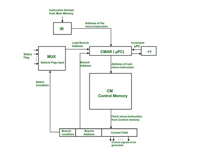
4. The Micro-instruction
If the Control Store is the "recipe book" for the CPU, then a micro-instruction is a single "line" in that recipe. It is the most fundamental unit of control in a microprogrammed CPU, defining the exact set of hardware operations that will occur in a single clock cycle.
-
4.1 Definition A micro-instruction is a single word fetched from the Control Store. Its primary function is to specify the control signals to be generated for one clock tick. Each micro-instruction is held in the Micro-instruction Register (uIR), and the bits of this register are used—either directly or after decoding—to activate or deactivate every control line in the CPU's datapath [1].
-
4.2 Format and Fields While the exact layout varies, a micro-instruction is typically divided into two primary types of fields [2].
-
4.2.1 Control Field: This is the main part of the micro-instruction. It contains the bits that directly control the datapath components. For example, a "1" in a specific bit position might enable a register to output its value to the main bus (like
RAO), while a "0" keeps it disabled. Another set of bits might specify the operation for the ALU (e.g.,SUB=1). -
4.2.2 Sequencing Field (Next Address Field): This field doesn't control the datapath; it controls the Micro-Sequencer itself. These bits provide the sequencer with information to determine the address of the next micro-instruction. This field might contain:
- A specific "next address" to jump to.
- A "branch condition" code (like
SEQ_DECODEorSEQ_JUMP_ON_ZERO) that tells the sequencer how to find the next address by checking opcodes or status flags [3].
-
-
4.3 Horizontal vs. Vertical Microprogramming The "Control Field" can be designed in two primary ways, which presents a classic trade-off between speed and memory efficiency [4].
-
4.3.1 Horizontal Microprogramming: This is a "decoded" or "unencoded" approach. The micro-instruction is very wide, and each bit in the control field corresponds directly to a single control line. If the CPU has 60 control signals, the control field is 60 bits wide.
- Pros: It is extremely fast. No additional decoding logic is needed; the bits from the uIR can be used directly. It also allows for high parallelism, as many signals can be activated in the same cycle.
- Cons: It is very inefficient. A micro-instruction that only activates 2 signals (e.g.,
RAOandRBI) still requires the full 60 bits, wasting space in the Control Store.
-
4.3.2 Vertical Microprogramming: This is an "encoded" approach. Instead of one bit per signal, groups of signals are encoded into fields. For example, if an ALU has 8 possible operations (ADD, SUB, AND, OR, etc.), a 3-bit field (
2^3 = 8) can be used to select which operation to perform.- Pros: It is highly efficient and saves a significant amount of space in the Control Store. The micro-instructions are much narrower.
- Cons: It is slower. The encoded fields (like the 3-bit ALU field) must be passed through an external decoder circuit to generate the final control signals, adding a layer of gate delay.
In practice, most modern designs are a hybrid, using vertical encoding for mutually exclusive signals (like ALU operations) and horizontal bits for independent signals (like
Memory_Write). -
5. Execution Flow and Sequencing
This section connects all the previous concepts to illustrate how the microprogrammed control unit runs a program. The core of this operation is the mapping of high-level assembly instructions to low-level micro-routines, all managed by the micro-sequencer.
- 5.1 Mapping Assembly to Micro-routines
-
The most important relationship in this design is the one-to-many mapping between an assembly instruction and its micro-routine. The main CPU's instruction set (the "assembly language") is not executed directly by the hardware; rather, each assembly instruction's opcode is a command that tells the micro-sequencer to find and run a specific "subroutine" of micro-instructions stored in the Control Store.
-
Hypothetical Example:
- Consider a CPU with registers
R0,R1, aPC,MAR,IR, andRAM. - A programmer writes the assembly instruction:
LOAD R0, [0x30] - This translates to the 8-bit machine code
0001 0011(Opcode0001forLOAD R0, and Address0011for0x30). - The Control Unit is designed to interpret this
0001opcode. This single assembly instruction triggers a multi-step micro-routine:
- Consider a CPU with registers
-
| Phase | Micro-operation | Keterangan |
|---|---|---|
| Fetch | uAddr 0: PC_out, MAR_in |
(Fetch CC1) Send PC to memory. |
uAddr 1: RAM_out, IR_in |
(Fetch CC2) Get instruction 00010011 into IR. |
|
| Decode | uAddr 1: (Sequencer Logic) |
Sequencer sees 0001, maps it to uAddr 16. |
| Execute | uAddr 16: IR_addr_out, MAR_in |
(Execute CC1) Get address 0011 from IR. |
uAddr 17: RAM_out, R0_in, PC_inc |
(Execute CC2) Get data from RAM[0x30] into R0. Increment PC. |
|
uAddr 17: (Sequencer Logic) |
Sequencer sees SEQ_FETCH, sets next_uPC = 0. |
-
5.2 The Fetch-Decode-Execute Cycle (Microprogram View)
-
From the micro-sequencer's perspective, the fetch-decode-execute cycle is a continuous loop of branching within its own Control Store [2].
-
1. Fetch: The micro-sequencer is hardwired to always start at a fixed address (e.g.,
uAddr 0) when a new instruction is needed. It then executes theFetchmicro-routine (e.g., atuAddr 0anduAddr 1). -
2. Decode: The final micro-instruction of the
Fetchroutine (atuAddr 1in our example) contains a specialSEQ_DECODEsequencing command. This command tells the micro-sequencer to stop incrementing and instead use theopcodefrom theIRas an input to its logic. This logic acts as a "mapping ROM," translating the opcode (e.g.,0001) into the starting address of its corresponding micro-routine (e.g.,uAddr 16). -
3. Execute: The micro-sequencer jumps to that new address (e.g.,
uAddr 16) and executes the micro-routine for the instruction. The final micro-instruction of that routine (e.g., atuAddr 17) then issues aSEQ_FETCHcommand, which forces the micro-sequencer to jump back touAddr 0and begin the entire process again for the next assembly instruction.
-
-
5.3 Conditional Branching (Sequencing with Flags)
-
The true power of a micro-sequencer is revealed in how it handles conditional branching (e.g.,
JUMP_IF_ZERO). This is not implemented with a new micro-instruction, but by adding logic to the sequencer'sDecodestep. -
The
SEQ_DECODEcommand is enhanced to not only look at theopcodebut also at the CPU'sStatus Flags(likeZero_FlagandCarry_Flag). -
Example (Hypothetical
JUMP_ZERO [ADDR], Opcode1010):- The programmer writes
CMP R0, R1(which sets theZero_Flag) followed byJUMP_ZERO 0x05. - When the
JUMP_ZEROinstruction (1010 0101) is fetched, the micro-sequencer'sDECODElogic executes the following:
if (opcode == "1010") then -- This is a JUMP_ZERO instruction if (Zero_Flag == '1') then next_uPC = uAddr_JUMP_ROUTINE; -- Jump to the JUMP micro-routine else next_uPC = uAddr_NOP_ROUTINE; -- Jump to the NOP micro-routine (to just inc PC) end if; else -- (handle other opcodes...) end if; - The programmer writes
-
In this way, the micro-sequencer dynamically selects the correct micro-routine—either
JMPorNOP—based on the current state of the CPU flags, effectively executing the conditional branch.
-
-
5.4 VHDL Code Example: A Hypothetical Microprogrammed Control Unit
The following VHDL code is a complete, behavioral model of a hypothetical microprogrammed control unit. This example is simplified to clearly demonstrate the core concepts of sequencing, mapping, and conditional branching.
This code directly illustrates the concepts from sections 5.1, 5.2, and 5.3.
- Mapping (5.1): The
init_romfunction shows how opcodes (like"0001") are "mapped" to the starting addresses of micro-routines (likeuAddr 20). - Fetch/Decode/Execute (5.2): The
next_uPCprocess (the Micro-Sequencer) implements this flow.SEQ_FETCH(atuAddr 0, 1) is theFetchphase.when SEQ_DECODE =>is theDecodephase, which reads theOPCODE_IN.- The resulting jump (e.g.,
next_uPC <= to_unsigned(20, 8)) is the start of theExecutephase.
- Conditional Branching (5.3): The
SEQ_DECODEblock contains the most important logic. It explicitly checks theZ_FLAGin addition to theOPCODE_INto implement aJUMP_IF_ZEROinstruction.
library IEEE;
use IEEE.std_logic_1164.all;
use IEEE.numeric_std.all;

entity Hypothetical_Micro_CU is
    port (
        CLK         : in  std_logic;
        RST         : in  std_logic;

        -- Inputs from Datapath
        OPCODE_IN   : in  std_logic_vector(3 downto 0);
        Z_FLAG      : in  std_logic; -- (for conditional jumps)

        -- Outputs to a hypothetical 10-signal datapath
        PC_OUT      : out std_logic := '0';
        PC_INC      : out std_logic := '0';
        MAR_IN      : out std_logic := '0';
        RAM_OUT     : out std_logic := '0';
        RAM_IN      : out std_logic := '0';
        IR_IN       : out std_logic := '0';
        ACC_IN      : out std_logic := '0';
        ACC_OUT     : out std_logic := '0';
        TEMP_IN     : out std_logic := '0';
        ALU_OUT     : out std_logic := '0'
    );
end entity;

architecture Behavioral of Hypothetical_Micro_CU is

    -- 3.2.2 Micro-Sequencer
    -- This is the "micro-Program Counter" (uPC)
    signal uPC      : unsigned(7 downto 0) := (others => '0');
    signal next_uPC : unsigned(7 downto 0);

    -- 3.2.3 Micro-instruction Register (uIR)
    -- 10 control bits + 2 sequencing bits
    signal uIR : std_logic_vector(11 downto 0);

    -- 4.2.2 Sequencing Field Constants
    constant SEQ_NEXT   : std_logic_vector(1 downto 0) := "00";
    constant SEQ_DECODE : std_logic_vector(1 downto 0) := "01";
    constant SEQ_FETCH  : std_logic_vector(1 downto 0) := "10";
    constant SEQ_HLT    : std_logic_vector(1 downto 0) := "11";

    -- 4.2 Format and Fields
    constant C_SEQ_BITS  : integer := 2;
    constant C_CTRL_BITS : integer := 10;
    constant C_UCODE_WIDTH : integer := C_SEQ_BITS + C_CTRL_BITS; -- 12 bits

    -- 3.2.1 Control Store (ROM)
    type t_control_store is array(0 to 255) of std_logic_vector(C_UCODE_WIDTH - 1 downto 0);

    -- Helper function to build a micro-instruction
    function to_ucode(
        ctrl : std_logic_vector(C_CTRL_BITS - 1 downto 0);
        seq  : std_logic_vector(C_SEQ_BITS - 1 downto 0)
    ) return std_logic_vector is
    begin
        return seq & ctrl; -- [Seq(1:0), Ctrl(9:0)]
    end function;

    -- Initialize the Control Store (ROM) with micro-routines
    function init_rom return t_control_store is
        variable rom : t_control_store := (others => (others => '0'));

        -- Control Field constants (10 bits)
        -- [PC_OUT, PC_INC, MAR_IN, RAM_OUT, RAM_IN, IR_IN, ACC_IN, ACC_OUT, TEMP_IN, ALU_OUT]
        constant C_FETCH1 : std_logic_vector(9 downto 0) := "1010000000"; -- PC_OUT, MAR_IN
        constant C_FETCH2 : std_logic_vector(9 downto 0) := "0001010000"; -- RAM_OUT, IR_IN
        constant C_LDA1   : std_logic_vector(9 downto 0) := "0010000000"; -- MAR_IN (assume from IR)
        constant C_LDA2   : std_logic_vector(9 downto 0) := "0101001000"; -- PC_INC, RAM_OUT, ACC_IN
        constant C_JUMP1  : std_logic_vector(9 downto 0) := "0000000000"; -- (Assume PCI/IRO logic)
        constant C_NOP1   : std_logic_vector(9 downto 0) := "0100000000"; -- PC_INC

    begin
        -- 5.2 Fetch Cycle
        rom(0) := to_ucode(C_FETCH1, SEQ_NEXT);   -- uAddr 0
        rom(1) := to_ucode(C_FETCH2, SEQ_DECODE); -- uAddr 1

        -- 5.1 Mapping Assembly to Micro-routines
        -- These are the "Execute" routines

        -- Map Opcode "0001" (LOAD_ACC) to uAddr 20
        rom(20) := to_ucode(C_LDA1, SEQ_NEXT);
        rom(21) := to_ucode(C_LDA2, SEQ_FETCH);

        -- Define targets for conditional branches
        rom(16) := to_ucode(C_NOP1, SEQ_FETCH);  -- uAddr 16 (NOP routine)
        rom(30) := to_ucode(C_JUMP1, SEQ_FETCH); -- uAddr 30 (JUMP routine)

        -- ... the rest of the ROM for other opcodes (ADD, STA, etc.) ...

        return rom;
    end function;

    -- Create the constant ROM
    constant Control_Store : t_control_store := init_rom;

    -- Define the jump targets for conditional branches
    constant uAddr_NOP_ROUTINE : unsigned(7 downto 0) := to_unsigned(16, 8);
    constant uAddr_JMP_ROUTINE : unsigned(7 downto 0) := to_unsigned(30, 8);

begin

    -- 1. Micro-Program Counter (uPC) Register (The "State")
    process(CLK)
    begin
        if rising_edge(CLK) then
            if RST = '1' then
                uPC <= (others => '0'); -- On reset, go to Fetch (uAddr 0)
            else
                uPC <= next_uPC;
            end if;
        end if;
    end process;

    -- 2. ROM Read (Concurrent)
    uIR <= Control_Store(to_integer(uPC));

    -- 3. Micro-Sequencer (Next uPC Logic)
    -- This process is the "brain" of the Control Unit
    process(uPC, uIR, OPCODE_IN, Z_FLAG)
        variable seq_control : std_logic_vector(1 downto 0);
    begin
        seq_control := uIR(C_UCODE_WIDTH - 1 downto C_CTRL_BITS);

        -- Default: always increment
        next_uPC <= uPC + 1;

        case seq_control is
            when SEQ_NEXT =>
                next_uPC <= uPC + 1;

            when SEQ_FETCH =>
                next_uPC <= (others => '0'); -- Go back to Fetch (uAddr 0)

            when SEQ_HLT =>
                next_uPC <= uPC; -- Halt by looping on this address

            when SEQ_DECODE =>
                -- This is the 5.2 Decode step
                -- It maps the opcode to a micro-routine address
                case OPCODE_IN is
                    when "0001" => -- LOAD_ACC
                        next_uPC <= to_unsigned(20, 8);

                    -- ... other non-branching opcodes (ADD, STA, etc.) ...

                    -- 5.3 Conditional Branching Logic
                    when "1010" => -- JUMP_IF_ZERO
                        if Z_FLAG = '1' then
                            next_uPC <= uAddr_JMP_ROUTINE;
                        else
                            next_uPC <= uAddr_NOP_ROUTINE;
                        end if;

                    -- ... other conditional branches (JNE, JLT, etc.) ...

                    when others =>
                        next_uPC <= uAddr_NOP_ROUTINE; -- Invalid opcode
                end case;

            when others =>
                next_uPC <= (others => '0'); -- Safe state
        end case;
    end process;

    -- 4. Output Logic (Concurrent)
    -- Map the 10 control bits from the uIR to the output ports
    PC_OUT  <= uIR(9);
    PC_INC  <= uIR(8);
    MAR_IN  <= uIR(7);
    RAM_OUT <= uIR(6);
    RAM_IN  <= uIR(5);
    IR_IN   <= uIR(4);
    ACC_IN  <= uIR(3);
    ACC_OUT <= uIR(2);
    TEMP_IN <= uIR(1);
    ALU_OUT <= uIR(0);

end Behavioral;
Module 10 - Final Project
Final Project Guide
Congratulations! 🥳
In this final module, you are given the opportunity to create a project with your group members according to the following provisions:
Final Project Timeline
- Github Link Deadline: Sunday, November 23, 2025 23.59 WIB
- Project Title: Discuss with the supervising assistant (Must be decided by Sunday, November 30, 2023)
- Project Submission Deadline: Sunday, December 7, 2025, 23:59 WIB
- Presentation Week: December 8-12, 2025 (discuss with the supervising assistant)
Final Project Criteria
- The final project must cover atleast 6 of the practicum modules. The program and testbench MUST use the VHDL language, including code explanations using comments.
- Create a public GitHub repository for project submission. Each individual must commit regularly so their individual contributions are visible in the final project (there will also be a contribution assessment form).
- You must invite the supervising assistant as a collaborator to the repo and to the LINE group.
- Force pushing to the repo is prohibited as it can delete commit history.
- You must create a README.md in the final project repository containing an explanation of your project. The sections can be the same as those in the report file, with the addition of code snippet explanations.
- Tutorial: Markdown Crash Course.
- Template: GitHub - matiassingers/awesome-readme
- Program complexity will affect the final project grade. If the project you create is limited to fulfilling module requirements and is less suitable for FPGA implementation, the grade will be lower than for one that is more suitable.
- Example of a less suitable (though not prohibited) project: Creating a Vending Machine can be implemented on an FPGA, or a DSD project you've done before can also be implemented with FPGA (VHDL). However, no one would implement something that simple on an FPGA because it's more practical to use an Arduino or another microcontroller.
- Example of a more suitable project: Creating a hardware accelerator for a specific, frequently used algorithm.
- Create a final project report based on the provided template.
- Create a presentation PowerPoint.
Final Project Grading Weight
- Report (PDF & MD): 15%
- Presentation (PPT, Delivery, & Q&A): 20%
- Complexity (including Understanding): 25%
- Idea Creativity: 10%
- Success/Functionality: 30%
Files and Submission Location
- EMAS3
- GitHub Link (submitted on EMAS)
- GitHub Repository
- PDF Report file
- PPT Presentation file
- Source code + Testbench
- Quartus Synthesis
- Modelsim waveform simulation
- README.md
Example Final Project Ideas*
- VHDL Image Processing: Modify an image (e.g., Rotation, Brightness, Flip).
- Source: https://github.com/juanjonathan67/Simple-Image-Augmenter
- VHDL Image Upscaler: Upscale an image.
- Source: https://github.com/Jordinia/Bicubic-Interpolation
- VHDL Enigma Encryption: Encrypt an input message.
- Source: https://github.com/ArmondHarer/Proyek-Akhir-PSD-B2
*Only use these three examples as a reference or for idea inspiration. Plagiarism is prohibited.