# Vivado Simulation and Synthesis Tutorial
## 1.3 Vivado Tutorial
For this tutorial, we will use this code for reference :
```
LIBRARY IEEE;
USE IEEE.STD_LOGIC_1164.ALL;
ENTITY AND_GATE IS
PORT (
A : IN STD_LOGIC;
B : IN STD_LOGIC;
Y : OUT STD_LOGIC
);
END AND_GATE;
ARCHITECTURE Behavioral OF AND_GATE IS
BEGIN
Y <= A AND B;
END Behavioral;
```
#### 1.3.1 Creating a new Vivado file
Create a new project
[](https://learn.digilabdte.com/uploads/images/gallery/2025-09/7T6image.png)
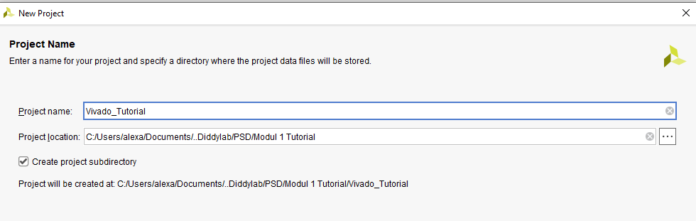
Enter your project name and where you want it to be saved
[](https://learn.digilabdte.com/uploads/images/gallery/2025-09/UdMimage.png)
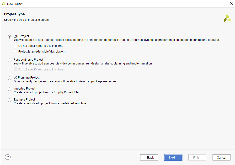
Choose RTL Project
[](https://learn.digilabdte.com/uploads/images/gallery/2025-09/HMUimage.png)
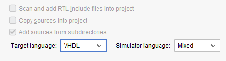
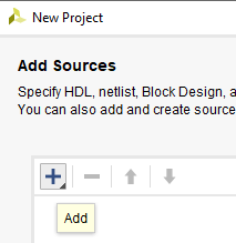
Change the target language into VHDL and add your VHDL code into the project
[](https://learn.digilabdte.com/uploads/images/gallery/2025-09/qhiimage.png)
[](https://learn.digilabdte.com/uploads/images/gallery/2025-09/dGCimage.png)
[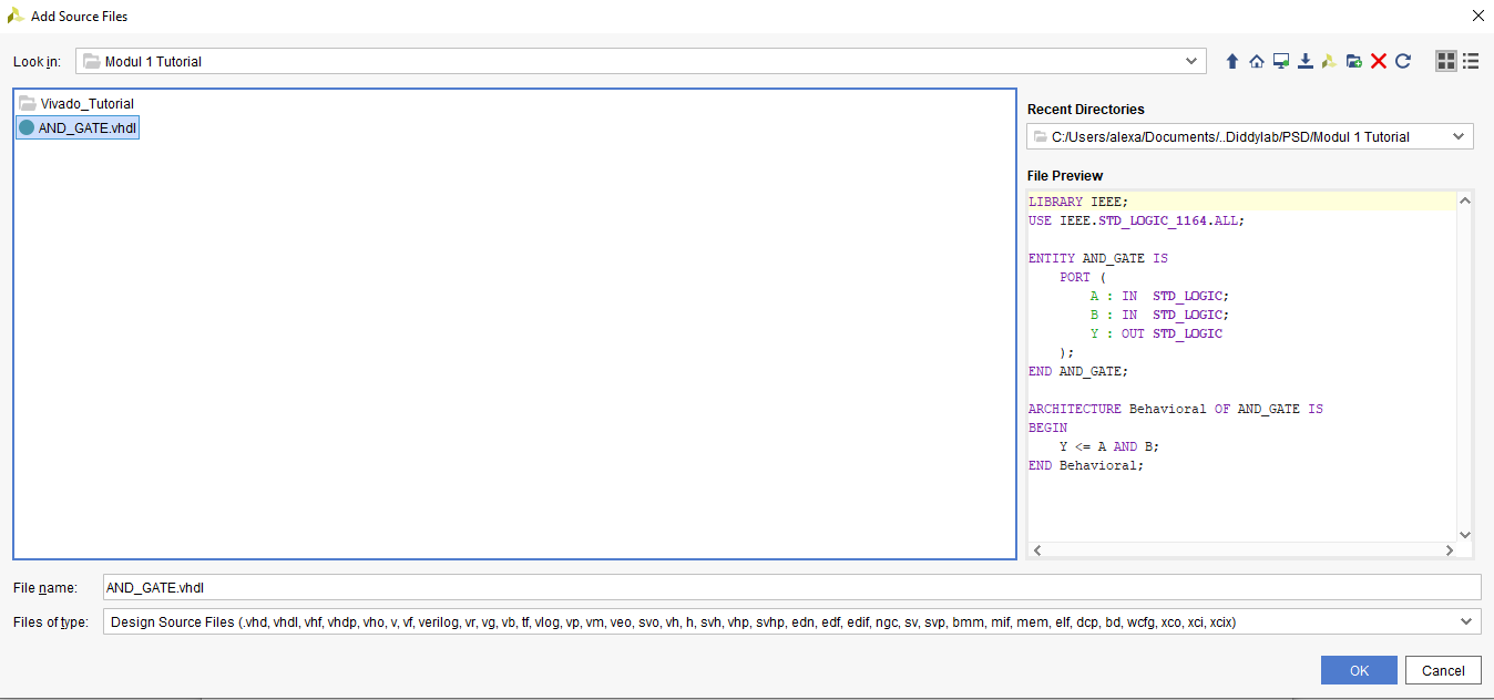](https://learn.digilabdte.com/uploads/images/gallery/2025-09/6drimage.png)
[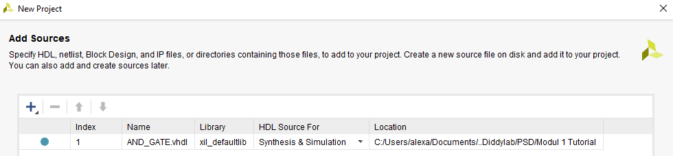](https://learn.digilabdte.com/uploads/images/gallery/2025-09/Raaimage.png)
You may skip the add constraints page and also the default part proceed into the project creation. Finally you've created a new project and this will be your screen now.
[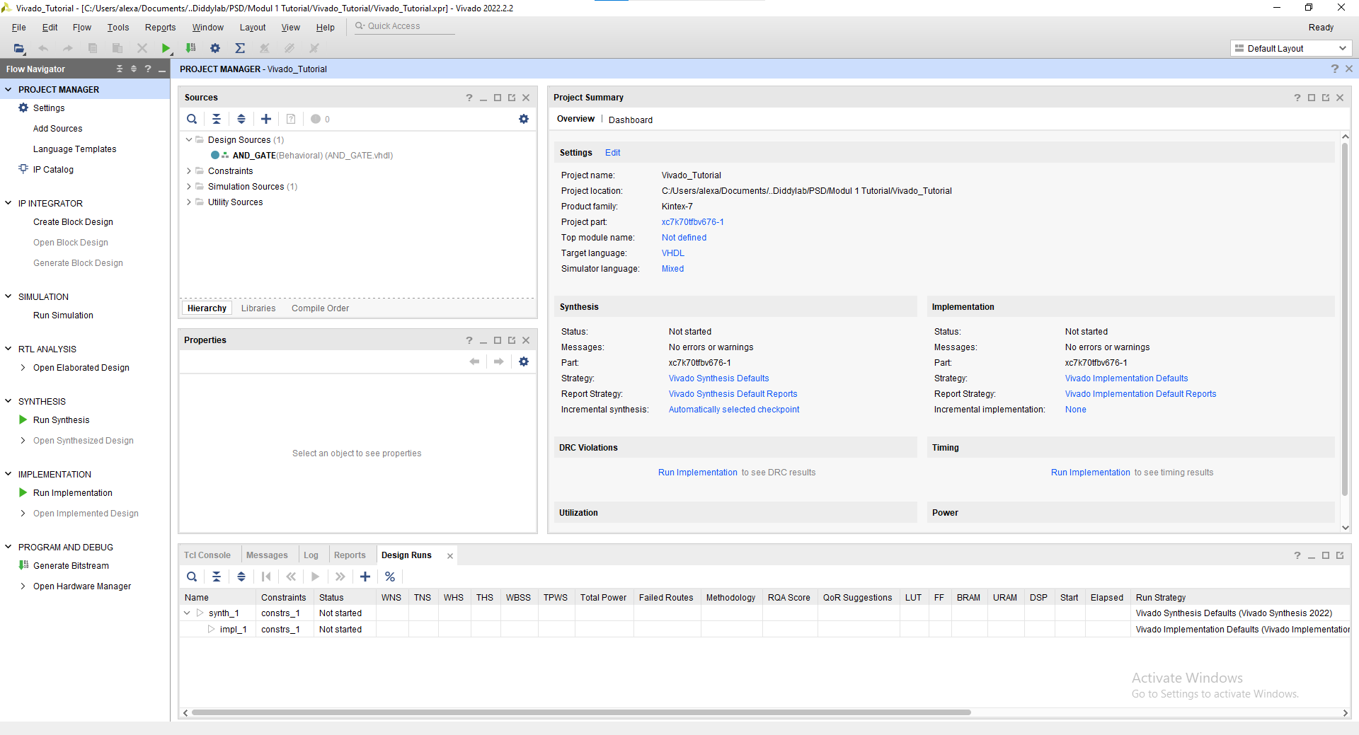](https://learn.digilabdte.com/uploads/images/gallery/2025-09/ZVZimage.png)
#### 1.3.2 Simulation Tutorial
Click "Run Simulation" on the left part of the screen. And choose "Run Behavorial Simulation"
[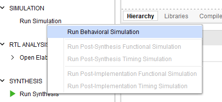](https://learn.digilabdte.com/uploads/images/gallery/2025-09/Bbzimage.png)
If there's any error warning, you may read and fix the error before proceeding into the simulation.
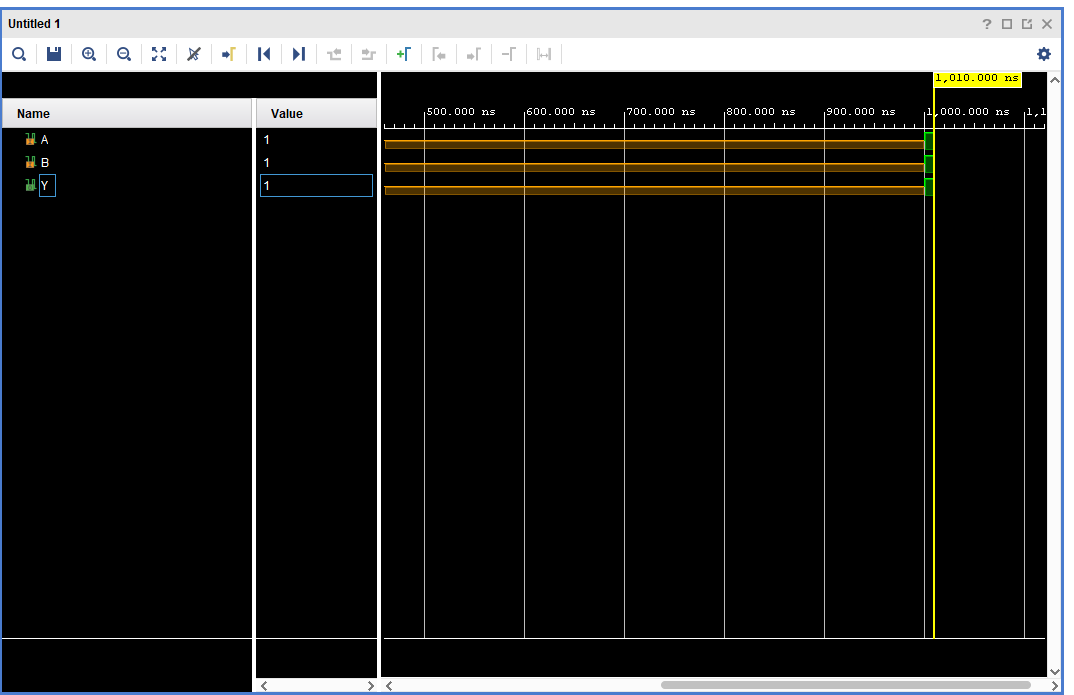
This will be your screen after you run the simulation.
[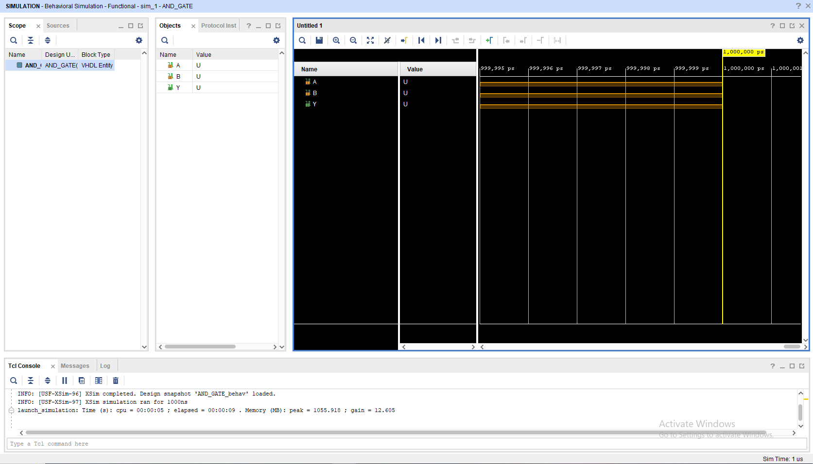](https://learn.digilabdte.com/uploads/images/gallery/2025-09/8UEimage.png)
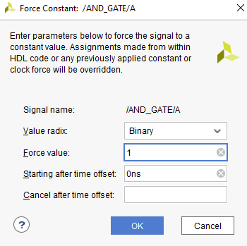
To add a signal, you may change the value in the objects part, choose "Force Constant" and change according to what you want to do. Remember to change the **INPUT **not the **OUTPUT**
[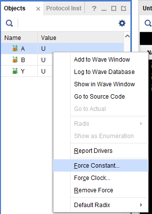](https://learn.digilabdte.com/uploads/images/gallery/2025-09/JxNimage.png)
[](https://learn.digilabdte.com/uploads/images/gallery/2025-09/EtZimage.png)
[](https://learn.digilabdte.com/uploads/images/gallery/2025-09/cr9image.png)
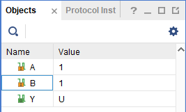
After changing the Value you may click the "Run for 10ns" on the top bar
[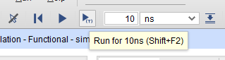](https://learn.digilabdte.com/uploads/images/gallery/2025-09/YZiimage.png)
You may see that there's a new signal after you press the button
[](https://learn.digilabdte.com/uploads/images/gallery/2025-09/RzQimage.png)
You may also move the yellow line with your cursor to switch to a different period of time on the waveform
[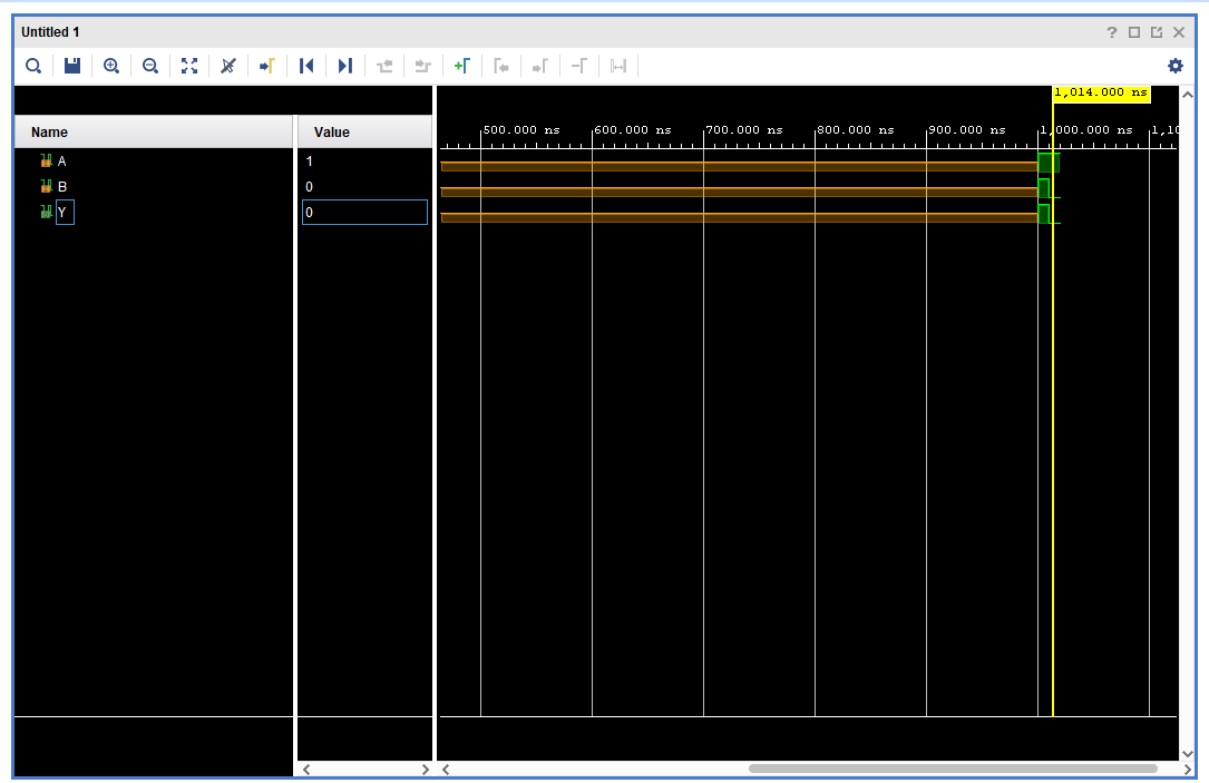](https://learn.digilabdte.com/uploads/images/gallery/2025-09/Snoimage.png)
##### NOTE : All of this is just a manual simulation tutorial. There are a way to do this automatically (Hint: Module 4).
To close simulation, you may click the top right button
[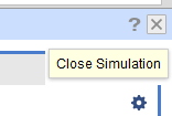](https://learn.digilabdte.com/uploads/images/gallery/2025-09/LbFimage.png)
#### 1.3.3 Synthesis Tutorial
Go to the "RTL Analysis" and run "Schematic" and if there's a notification just select "ok"
[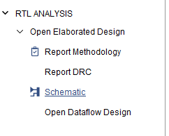](https://learn.digilabdte.com/uploads/images/gallery/2025-09/ieqimage.png)
Wait until the elaborated design is finished and then you may see your VHDL code schematic.
[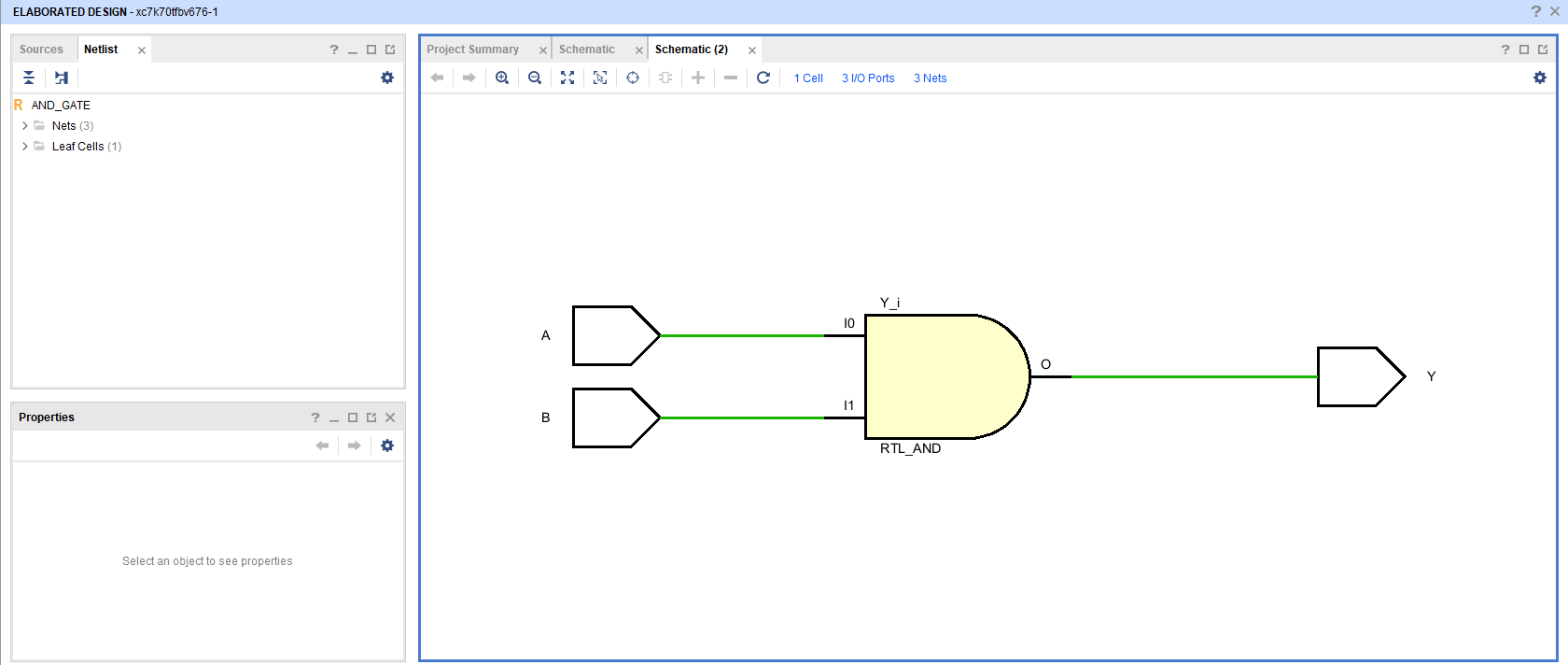](https://learn.digilabdte.com/uploads/images/gallery/2025-09/CJmimage.png)