FSM Implementation Example in VHDL
Moore Machine
This FSM has two states: ST0 and ST1. In the ST0 state, the FSM outputs '0', and in ST1, the output is '1'. This FSM also accepts two inputs: CLR and TOG_EN. The CLR input returns the FSM to ST0, while TOG_EN determines whether the FSM can switch states.

library IEEE;
use IEEE.STD_LOGIC_1164.ALL;

entity FSM_Moore is
    Port ( CLK : in STD_LOGIC;
           CLR : in STD_LOGIC;
           TOG_EN : in STD_LOGIC;
           Z1 : out STD_LOGIC);
end FSM_Moore;

architecture Behavioral of FSM_Moore is
    type state_type is (ST0, ST1);
    signal state, next_state : state_type;
begin
    process (CLK, CLR)
    begin
        if CLR = '1' then
            state <= ST0;
        elsif rising_edge(CLK) then
            state <= next_state;
        end if;
    end process;

    process (state, TOG_EN)
    begin
        case state is
            when ST0 =>
                if TOG_EN = '1' then
                    next_state <= ST1;
                else
                    next_state <= ST0;
                end if;
            when ST1 =>
                if TOG_EN = '1' then
                    next_state <= ST0;
                else
                    next_state <= ST1;
                end if;
        end case;
    end process;

    process (state)
    begin
        case state is
            when ST0 =>
                Z1 <= '0';
            when ST1 =>
                Z1 <= '1';
        end case;
    end process;
end Behavioral;
Penjelasan Kode
- In the code above, we define the FSM_Moore entity with three inputs (CLK, CLR, TOG_EN) and one output (Z1).
- In the Behavioral architecture, we define a state_type data type that contains two states: ST0 and ST1. In addition, we define two signals state and next_state of type state_type.
- In the first process, we use the state and next_state signals to set the state transition based on the input received. If the input CLR = '1', the FSM will return to the ST0 state. If the CLK input changes from '0' to '1', the FSM will move to the next_state.
- In the second process, we use the state and TOG_EN signals to set the output based on the current state and the input received. If the FSM is in state ST0 and input TOG_EN = '1', then the FSM will move to state ST1. If the FSM is in the ST1 state and the TOG_EN input = '1', then the FSM will move to the ST0 state.
- In the third process, we use state signals to set the output based on the current state. If the FSM is in the ST0 state, then the output is '0'. If the FSM is in the ST1 state, then the output is '1'.
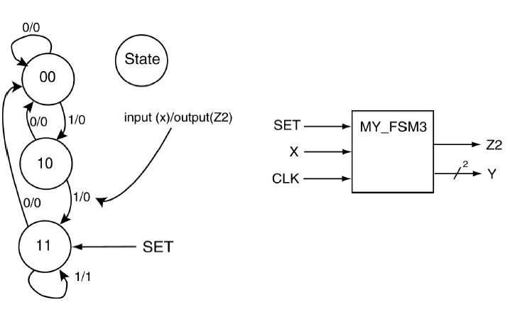
Mealy Machine
This FSM has three states: “00”, ‘01’, and ‘11’. In addition, this FSM accepts two inputs: SET and X. The SET input returns the FSM to state “11”, while X determines the next output and state
library IEEE;
use IEEE.STD_LOGIC_1164.ALL;

entity FSM_Mealy is
    Port ( CLK : in STD_LOGIC;
           SET : in STD_LOGIC;
           X : in STD_LOGIC;
           Y : out STD_LOGIC_VECTOR (1 downto 0);
           Z2 : out STD_LOGIC);
end FSM_Mealy;

architecture Behavioral of FSM_Mealy is
    type state_type is (ST00, ST01, ST11);
    signal state, next_state : state_type;
begin
    process (CLK, SET)
    begin
        if SET = '1' then
            state <= ST11;
        elsif rising_edge(CLK) then
            state <= next_state;
        end if;
    end process;

    process (state, X)
    begin
        case state is
            when ST00 =>
                if X = '0' then
                    next_state <= ST00;
                else
                    next_state <= ST01;
                end if;
            when ST01 =>
                if X = '0' then
                    next_state <= ST00;
                else
                    next_state <= ST11;
                end if;
            when ST11 =>
                next_state <= ST11;
        end case;
    end process;

    process (state, X)
    begin
        case state is
            when ST00 =>
                Y <= "00";
                Z2 <= '0';
            when ST01 =>
                Y <= "01";
                Z2 <= '1';
            when ST11 =>
                Y <= "11";
                Z2 <= X;
        end case;
    end process;
end Behavioral;
Penjelasan Kode
- In the code above, we define the FSM_Mealy entity with four inputs (CLK, SET, X) and two outputs (Y, Z2).
- In the Behavioral architecture, we define a state_type data type that contains three states: ST00, ST01, and ST11. In addition, we define two signals state and next_state of type state_type.
- In the first process, we use the state and next_state signals to set the state transition based on the input received. If the SET input = '1', the FSM will return to the ST11 state. If the CLK input changes from '0' to '1', the FSM will move to the next_state.
- In the second process, we use the state and X signals to set the output and state transition based on the current state and the received input. If the FSM is in state ST00 and input X = '0', then the FSM will remain in state ST00. If the FSM is in state ST00 and input X = '1', then the FSM will move to state ST01. If the FSM is in state ST01 and input X = '0', the FSM will move to state ST00. If the FSM is in state ST01 and input X = '1', the FSM will move to state ST11. If the FSM is in state ST11, the FSM will remain in state ST11.
- In the third process, we use the state and X signals to set the output based on the current state and the received input. If the FSM is in state ST00, then output Y is “00” and output Z2 is '0'. If the FSM is in the ST01 state, then the Y output is “01” and the Z2 output is '1'. If the FSM is in the ST11 state, then the Y output is “11” and the Z2 output is X.