2. Operating Modes
2.1. Normal Mode

In Normal Mode, the timer acts as a simple up-counter. It starts from 0 and increments with every clock pulse (after passing through the prescaler) until it reaches its maximum value (0xFF for 8-bit, 0xFFFF for 16-bit.
Once it hits the maximum, it "rolls over" or overflows back to 0. Upon overflow, the Timer Overflow Flag (TOVn) is set, which can trigger an Interrupt Service Routine (ISR). This is perfect for tracking elapsed time by incrementing a software counter every time an overflow occurs.
Formula for Overflow Frequency:
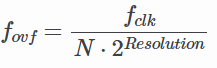
where N is the prescaler value.
2.2. CTC (Clear Timer on Compare) Mode

CTC Mode is far more precise for generating specific frequencies. Instead of waiting for an overflow at the maximum possible value, the timer counts until it matches a value you pre-defined in the Output Compare Register (OCRnx). As soon as the match occurs, the timer clears itself (resets to 0).
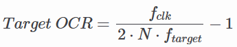
You can configure the timer to "toggle" an output pin automatically when the match occurs, creating a perfect square wave without CPU intervention. For example, to generate a 1 kHz square wave using a 16 MHz clock and a 64 prescaler, you would calculate the required OCR value:
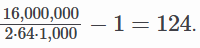
Using the values above:
2.3. PWM (Pulse Width Modulation) Mode
PWM Mode is used to simulate an analog output using digital signals. By rapidly switching a pin between HIGH and LOW, you can control the average power delivered to a component.
- Fast PWM: High frequency, suitable for power regulation and LED dimming. The timer counts from 0 to MAX, resetting to 0 immediately. The output pin changes state when the timer reaches the OCR value.
- Phase Correct PWM: Provides a symmetrical waveform by counting up to MAX and then counting back down to 0. This is preferred for motor control as it reduces electromagnetic noise. Duty Cycle: Controlled by the value in the OCR register. A higher value means the signal stays "HIGH" longer within one period.