# Module 4 - Complex Logic Gates
A complex logic gate is a digital circuit component that performs a logical function built from a combination of basic logic gates like AND, OR, and NOT. The most commonly used complex gates are NAND (Not-AND), NOR (Not-OR), XOR (Exclusive-OR), and XNOR (Exclusive-NOR).
The primary advantage of using complex gates is to simplify digital circuit design. By combining the functions of multiple basic gates into a single component, complex gates help reduce the total number of Integrated Circuits (ICs) needed to build a circuit. This makes the final circuit more compact, often more power-efficient, and potentially faster.
# Complex Logic ICs
### IC Functions, Pin Configurations, and Truth Tables
#### IC 7400: Quad 2-Input NAND Gate
**Function:** The IC 7400 contains four independent 2-input NAND gates in a single package. You can use any of these four gates separately.\
**Boolean Expression:** The logical function of a NAND gate is represented as `F = (AB)'`
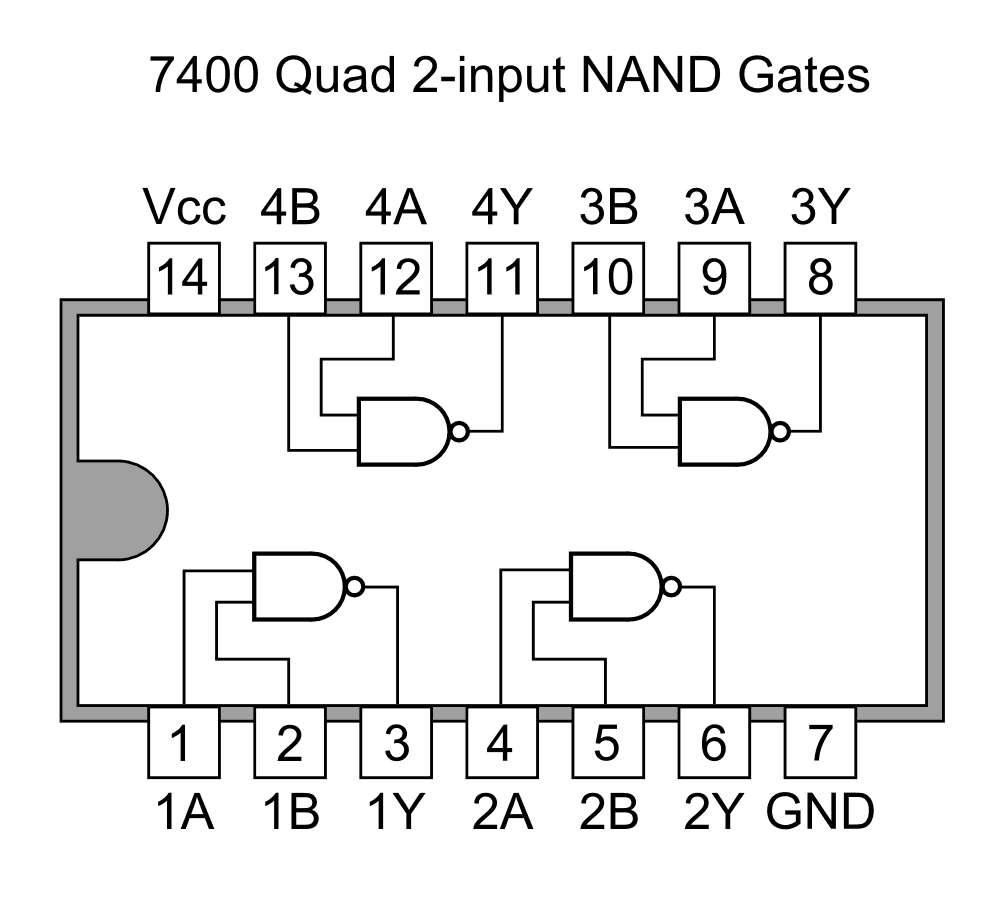
**Pin Configuration:** This IC has 14 pins.\
Pin 7: Ground connection (GND).\
Pin 14: Positive power supply (+5V, VCC).\
Gate 1: Pins 1 & 2 are inputs, Pin 3 is the output.\
Gate 2: Pins 4 & 5 are inputs, Pin 6 is the output.\
Gate 3: Pins 9 & 10 are inputs, Pin 8 is the output.\
Gate 4: Pins 12 & 13 are inputs, Pin 11 is the output.
**Truth Table:** The output is 0 only when both inputs are 1.
| Input A | Input B | Output Y |
|---------|---------|----------|
| 0 | 0 | 1 |
| 0 | 1 | 1 |
| 1 | 0 | 1 |
| 1 | 1 | 0 |
#### IC 7402: Quad 2-Input NOR Gate
**Function:** The IC 7402 contains four independent 2-input NOR gates.\
**Boolean Expression:** The logical function of a NOR gate is represented as `F = (A + B)'`
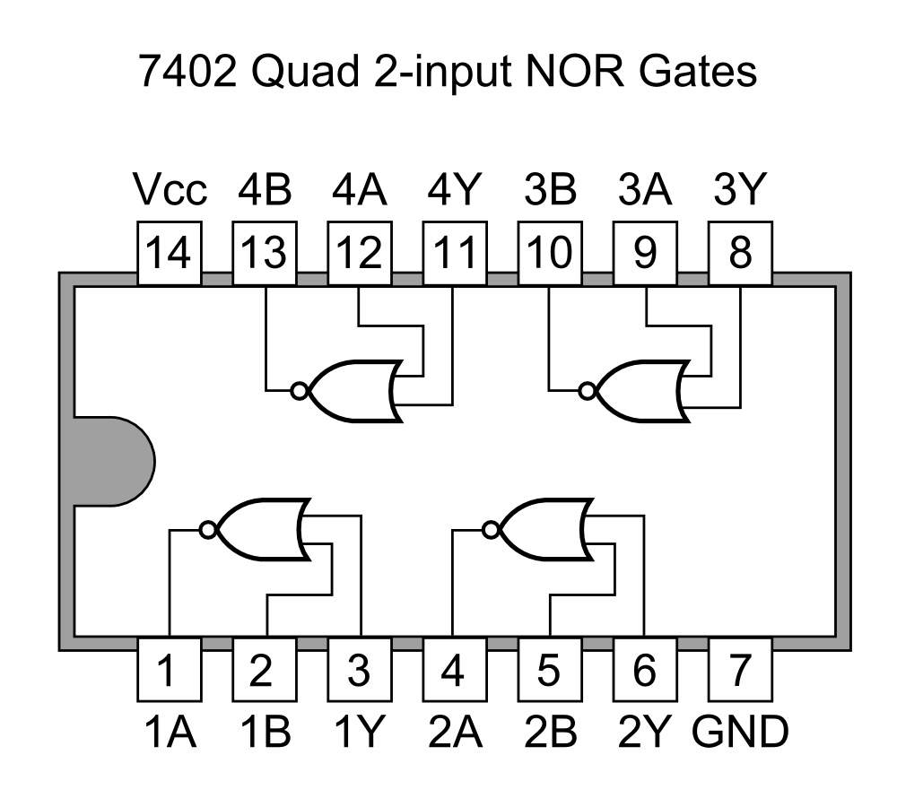
**Pin Configuration:** This 14-pin IC has a slightly **`different pinout`**.\
Pin 7: Ground connection (GND).\
Pin 14: Positive power supply (+5V, VCC).\
Gate 1: Pins 2 & 3 are inputs, Pin 1 is the output.\
Gate 2: Pins 5 & 6 are inputs, Pin 4 is the output.\
Gate 3: Pins 8 & 9 are inputs, Pin 10 is the output.\
Gate 4: Pins 11 & 12 are inputs, Pin 13 is the output.
**Truth Table:** The output is 1 only when both inputs are 0.
| Input A | Input B | Output Y |
|---------|---------|----------|
| 0 | 0 | 1 |
| 0 | 1 | 0 |
| 1 | 0 | 0 |
| 1 | 1 | 0 |
#### IC 7486: Quad 2-Input XOR Gate
**Function:** The IC 7486 contains four independent 2-input XOR (Exclusive-OR) gates.\
**Boolean Expression:** The logical function of a NAND gate is represented as `F = A'B + AB'`

**Pin Configuration:** The pinout for the 7486 is identical to the 7400.\
Pin 7: Ground connection (GND).\
Pin 14: Positive power supply (+5V, VCC).\
Gate 1: Pins 1 & 2 are inputs, Pin 3 is the output.\
Gate 2: Pins 4 & 5 are inputs, Pin 6 is the output.\
Gate 3: Pins 9 & 10 are inputs, Pin 8 is the output.\
Gate 4: Pins 12 & 13 are inputs, Pin 11 is the output.
**Truth Table:** The output is 1 only when the inputs are different.
| Input A | Input B | Output Y |
|---------|---------|----------|
| 0 | 0 | 0 |
| 0 | 1 | 1 |
| 1 | 0 | 1 |
| 1 | 1 | 0 |
#### IC 74266: Quad 2-Input XNOR Gate
**Function:** The IC 74266 contains four independent 2-input XNOR gates.\
**Boolean Expression:** The logical function of a NAND gate is represented as `F = AB + A'B'`

**Pin Configuration:** This 14-pin IC has a slightly **`different pinout`**.\
Pin 7: Ground connection (GND).\
Pin 14: Positive power supply (+5V, VCC).\
Gate 1: Pins 1 & 2 are inputs, Pin 3 is the output.\
Gate 2: Pins 5 & 6 are inputs, Pin 4 is the output.\
Gate 3: Pins 8 & 9 are inputs, Pin 10 is the output.\
Gate 4: Pins 12 & 13 are inputs, Pin 11 is the output.
**Truth Table:** The output is 1 only when the inputs are same.
| Input A | Input B | Output Y |
|---------|---------|----------|
| 0 | 0 | 1 |
| 0 | 1 | 0 |
| 1 | 0 | 0 |
| 1 | 1 | 1 |
# Complex vs Basic
### Advantages of Complex vs Basic Logic Gates
Using complex logic gates (like NAND, NOR, XOR) offers several significant advantages over building the same logic using only basic gates (AND, OR, NOT).
- **Reduced IC Count:** A single complex gate can perform the function of multiple basic gates. This means fewer physical chips are needed to build a circuit, which saves space on the circuit board.
- **Simplified Design:** Circuits built with fewer components are generally easier to design, read, and troubleshoot. The wiring is less complex, reducing the chances of errors.
- **Lower Cost:** Fewer ICs mean lower overall component cost for a project.
- **Increased Speed:** Every logic gate introduces a small time delay called "propagation delay." By reducing the total number of gates a signal must pass through, complex gates can often make the circuit operate faster.
- **Lower Power Consumption:** Since fewer ICs are used, the total power consumed by the circuit is typically lower.
# Complex is Universal
### Building Basic Gates from Universal Gates
NAND and NOR gates are called **universal gates** because any other logic function can be created using only one type of these gates.
#### Using Only NAND Gates
- **NOT Gate from NAND:** To create a NOT gate (an inverter), connect the two inputs of a single NAND gate together. This combined connection becomes the single input for your new NOT gate.
- **AND Gate from NAND:** To create an AND gate, use two NAND gates. First, connect your inputs (A and B) to the first NAND gate. The output of this gate is then connected to both inputs of a second NAND gate (which acts as a NOT gate). The final output is the AND function.
- **OR Gate from NAND:** To create an OR gate, use three NAND gates. First, create two separate NOT gates (one for input A, one for input B) by connecting the inputs of two NAND gates. Then, connect the outputs of these two inverters to the inputs of a third NAND gate.
#### Using Only NOR Gates
- **NOT Gate from NOR:** To create a NOT gate, connect the two inputs of a single NOR gate together.
- **OR Gate from NOR:** To create an OR gate, use two NOR gates. Connect your inputs (A and B) to the first NOR gate. Then, connect the output of that gate to both inputs of a second NOR gate (acting as a NOT gate).
- **AND Gate from NOR:** To create an AND gate, use three NOR gates. First, create two NOT gates (one for input A, one for input B). Connect the outputs of these inverters to the inputs of a third NOR gate.
| Gate | F = A + B | F = AB | F = A' |
|------|-----------|--------|--------|
| OR Gate |  | - | - |
| AND Gate | - |  | - |
| NOT Gate | - | - | 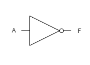 |
| NOR Gate |  | 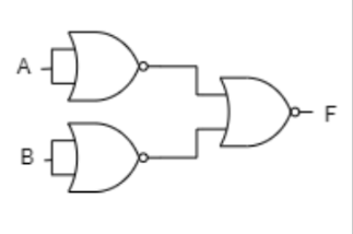 | 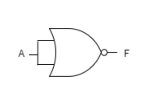 |
| NAND Gate | 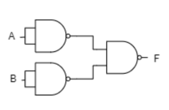 | 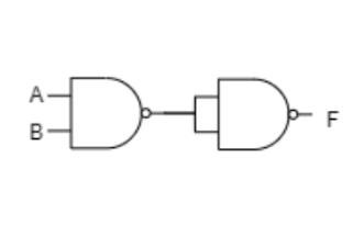 | 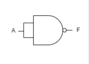 |