Internet of Things
- PlatformIO Guide
- Module 1 - Introduction to SMP with RTOS
- 1.1 Learning Objectives
- 1.2 Introduction to RTOS
- 1.3 Microcontroller Architecture
- 1.4 FreeRTOS
- 1.5 Additional References
- Module 2 - Task Management
- Learning Objectives
- The Importance of Task Scheduling in IoT
- Categories of Task Scheduling Algorithms
- Introduction to FreeRTOS
- Practical Sections
- Additional References
- Module 3 - Memory Management & Queue
- Tujuan Pembelajaran
- Why Memory Management?
- Tipe Memory Allocation
- Heap Configuration FreeRTOS
- Queue
- Mengirimkan Struct dengan Queue
- Referensi Lebih Lanjut
- Module 4 - Deadlock & Synchronization
- 4.1 Learning Objectives
- 4.2 Introduction: The Problem of Shared Resource Access
- 4.3 Synchronization Mechanisms in FreeRTOS
- 4.4 Common Problems in Synchronization
- 4.5 Prevention and Handling Strategies
- Module 5 - Software Timer
- 5.1 Introduction to Real-Time Multitasking
- 5.2 An Overview of Asynchronous Tools in FreeRTOS
- 5.3 Deep Dive: FreeRTOS Software Timers
- 5.4 Deep Dive: ESP32 Hardware Interrupts
- 5.5 The Core Challenge: ISRs and Tasks Synchronization
- 5.6 Synchronization Mechanisms: A Comparative Guide
- 5.7 Choosing the Right Tool: A Practical Comparison
- 5.8 Advanced Project: A Multi-Sensor Data Logger
- Module 6 - Bluetooth & BLE
- 6.1 Introduction to Bluetooth Technology
- 6.2 Core Specifications and Evolution
- 6.3 Core Technology Architectures
- 6.4 Bluetooth Audio: From Classic to Auracast™ (Optional)
- 6.5 High-Accuracy Location Services (Optional)
- 6.6 Bluetooth and the Internet of Things (IoT)
- 6.7 Bluetooth Security
- 6.8 The Bluetooth Protocol Stack
- 6.9 Practical Implementation with ESP32
- 6.10 Real-World Applications and The Future
- Module 7 - MQTT, HTTP, WIFI
- 7.1 Introduction: The IoT Communication Stack
- 7.2 Local Network Connectivity with Wi-Fi
- 7.3 Web Communication with HTTP/HTTPS
- 7.4 Efficient IoT Messaging with MQTT
- Module 8 - Power Management
- Tujuan Pembelajaran
- Konsumsi Daya pada ESP-32
- Metode Mengurangi Konsumsi Daya ESP-32 : Mengurangi Clock Speed CPU
- Metode Mengurangi Konsumsi Daya ESP-32 : Mengganti Operating Mode
- Referensi Lebih Lanjut
- Module 9 - IoT Platforms, Blynk, and Red Node
- Module 10 - Mesh
PlatformIO Guide
About
PlatformIO is a versatile, open-source ecosystem designed for embedded development, providing a unified platform for building, managing, and debugging firmware across a wide range of microcontroller architectures. Integrated with popular IDEs like VSCode and Atom, it offers powerful tools for code editing, dependency management, and cross-compilation. PlatformIO simplifies the development process with its rich library ecosystem, support for multiple frameworks, and seamless integration with version control systems, making it an invaluable tool for both hobbyists and professionals in the embedded systems community.
Install PlatformIO
1. Install VScode
If you haven't already, install VSCode on your machine. Download Here
2. Install PlatformIO Extension
After you've finished installing and setting up VSCode, open the Extensions menu, search for PlatformIO, and then install it.

Creating A New Project
1. Open the Projects & Configurations Tab
Open the PlatformIO menu. Then, within the Quick Access tab, select the Projects & Configurations tab.

2. Click Create New Project and Follow the Project Wizard
Click the Create New Project button, then fill out the required fields for the project.
First, set the name of the project.

Second, choose the board you want to use. In this example it will be DOIT ESP32 DEVKIT V1

Third, choose which framework you want to develop in. In this example, it will be the default choice, which is the Arduino framework.

(Optional) Uncheck the Use default location checkbox and choose the project location.

Lastly, click Finish
3. Open the Created Project
The project should be opened automatically, but if not, open it in the Projects & Configurations tab, similar to step 1.

Once the project is opened. Navigate to src/main.cpp file via the Explorer tab.

And done. This main.cpp file will be where you'll be coding your project, similar to a .ino file in the Arduino IDE.
Choosing Ports
By default, PlatformIO automatically chooses the correct port to upload your code to your board. Most of the time, it works. But if it doesn't work or maybe you have 2 or more boards connected, here's how you can choose the port of your active board.
1. Click the Port Button
Click the Set upload/monitor/test port button at the bottom.

2. Select an Active Port
Choose the port connected to your machine. Its most likely described as either CP210x or CH340.

Choosing a Project Environtment
If you have more that 1 project, you need to choose a default project so that PlatformIO knows which project are you currently working on.
1. Choose the Project Button
Click the Switch PlatformIO Project Environtment button at the bottom.

2. Choose a Project
Choose the project you want to work on. Utilize the search feature to ease your searching.

Uploading Code
Make sure that your port and project environtment is configured properly. Follow the steps above if you haven't done this already.
1. Click the Upload Button
Click the Upload Button

2. Hold the Boot Button on ESP32 if using an ESP32
Wait for your code to be compiled first. Then, when the connecting........ appears, hold the boot button on the ESP32 until the uploading process is complete.


Serial Monitor
1. Configure the Serial Baud Rate
monitor_speed = [Your baud rate]
Example :
monitor_speed = 115200

2. Click the Serial Monitor Button
Wait for the project to update, then click the Serial Monitor button.

Installing Libraries
You can install any library from PlatformIO.
1. Open the Libraries Page
Click the PlatformIO button, then open the Libraries Page

2. Search for a Library
Search for the Library you need

3. Add to Project
Click the Add to Project button. From this page, you can also view code examples, link to github repo, etc.

4. Choose Project
Choose the project you want to add the library. Then, click Add

5. Check the .ini File
Check if the lib_deps line is added. Save the file (Ctrl + S) if your file doesn't autosave.

6. Press the Build Button
Build the project so you can have code auto-completion.

7. Include the Project
Include the header file and you code auto-completion should work. Then, you can freely use the libary.


Module 1 - Introduction to SMP with RTOS
1.1 Learning Objectives
After completing this module, students are expected to be able to:
- Understand the difference between a General-Purpose Operating System (GPOS) and a Real-Time Operating System (RTOS)
- Understand the differences and benefits of Multi-Threading on a Microcontroller
- Understand the specifications of the ESP-32 as a microcontroller for IoT purposes
What Will We Learn?
In previous courses, you may already be familiar with Operating Systems (OS) and the use of Microcontrollers for Cyber-Physical Systems.
In those two cases, you used Linux, a General-Purpose Operating System (GPOS), and programmed using Arduino with a bare-metal architecture (running directly on the hardware without an OS).
In this IoT practicum, we will introduce the Real-Time Operating System (RTOS), a crucial architecture in embedded systems and IoT applications.
1.2 Introduction to RTOS
GPOS
The types of OS we often use (Windows, Linux, Mac, Android, iOS) can be classified as GPOS, which, as the name suggests, are designed for general purposes and typically utilize a GUI or CLI as the human interaction interface.
GPOS systems are designed to run multiple processes simultaneously, generally supported by multitasking and multi-threading, allowing the user to run several tasks at once. In general, timing deadlines for tasks in a GPOS are not crucial, and delays in tasks can be tolerated as long as they are not noticeable to the user[1]. For example, when a user opens a PDF document while listening to music on Spotify, both applications can run concurrently. If the system experiences a slight delay, such as the PDF page rendering taking longer or the audio buffering for a moment, this is still tolerable and does not significantly disrupt the user experience.
GPOS is non-deterministic, meaning the OS does not guarantee that a task will be fully completed within its allocated time (non-strict deadlines) [2]. This is not an issue for everyday GPOS applications that do not require strict timing certainty.
RTOS
Unlike GPOS, an RTOS plays a critical role in certain real-world applications. Imagine you are designing a car's airbag system, where the system must process sensor data with extreme speed and accuracy during a collision, then immediately deploy the airbag within microseconds. Even a slight delay could be fatal, thus requiring an operating system capable of guaranteeing real-time responses and consistently meeting strict deadlines.
Generally, an RTOS is designed to run on a microcontroller that does not have a user interface (GUI / CLI). The main advantage of an RTOS is its deterministic scheduling method, meaning the start time of a task can be known before it begins [1]. This ensures the timeliness of task execution, allowing the system to respond to events consistently, which is often crucial in IoT or embedded systems applications.
1.3 Microcontroller Architecture
Besides the differences in the type of OS used, there are also differences in the microcontrollers used. In this IoT lab, the ESP-32 microcontroller is used, which differs from the Arduino Uno used in the Embedded Systems lab. Look at the table below for a comparison between the two microcontrollers. [3]

In addition to the increase in RAM and wireless communication modules, a key difference between the ESP32 and the Arduino UNO is the number of cores.
This means the ESP32 can achieve true parallelism in executing its tasks.
Why is this important?
First, let's look at the program structure used on the Arduino Uno, which lacks parallelism and runs on bare metal, often using a "Superloop" architecture. In this architecture, a single setup process is performed to initialize components before entering a loop that executes all tasks. During the loop, interrupts can be processed based on external events. For many use cases, this architectural structure is sufficient to complete the required tasks.

Tasks in this architecture are executed sequentially. Consequently, if there are many tasks to run, there is a possibility of missing deadlines.
For example, if you create a device to read sensor data (like temperature or heart rate) and simultaneously upload it in real-time to a server via a WiFi connection, the superloop architecture on an Arduino Uno would struggle. This is because the process of communicating with the server (e.g., an HTTP request) takes a relatively long time and will block the main loop. As a result, sensor readings could be delayed or even missed entirely. This means that if sensor data needs to be read with precision (e.g., every few microseconds or milliseconds), this architecture cannot guarantee that timing.
The Solution?
The ESP-32 can leverage parallelism to complete these tasks so they run concurrently.
GPOS systems are designed to run multiple processes at once, commonly supported by multi-tasking and multi-threading, so the user can execute several tasks simultaneously. In general, timing deadlines for tasks on a GPOS are not crucial, and delays can be tolerated as long as they are not visible to the user.
In this context, the RTOS acts as the operating system that manages resource allocation and scheduling for each task. [1].

Based on the image above, an RTOS can divide program execution into several tasks. For instance, Task 1 is responsible for reading data from a sensor, Task 2 is responsible for uploading data to a server, while Task 3 can be used for a periodic process like logging.
Each task has its own priority, and through the RTOS API, we can configure it to run on a specific thread or schedule it as needed. In this way, the RTOS ensures that each task can be executed concurrently and on schedule, without interfering with each other.
This does not mean the number of tasks in an RTOS is limited to the two cores of the ESP-32. Rather, the RTOS can manage priorities and perform event scheduling and time-slicing to ensure the timeliness and deadlines of each task are met according to its priority.
Takeaway
Although an RTOS offers many advantages, it doesn't mean the bare-metal (super loop) architecture is always unsuitable. On 8-bit microcontrollers like the Arduino UNO (ATmega328p), the bare-metal approach is actually more efficient because the overhead of an RTOS scheduler is too large for the available resources. With bare metal, simple applications like reading a sensor, turning on an LED, or serial communication can run more lightly without additional overhead. Consequently, microcontrollers that utilize an RTOS tend to have higher minimum specifications.

When moving to more powerful microcontrollers like the ESP32, the use of an RTOS becomes increasingly relevant. Besides having dual-core capabilities, the ESP32 is designed for IoT applications, thus requiring multitasking capabilities so that the WiFi and Bluetooth stacks can run concurrently with the user's application, while also ensuring the deadlines of its operations are met.
1.4 FreeRTOS
So what is FreeRTOS? [4]
FreeRTOS is one of the most widely used RTOS implementations in the world of embedded systems and IoT. As its name implies, FreeRTOS is open-source and free to use.
Based on the previous explanation of RTOS, FreeRTOS acts as a lightweight OS that runs on a microcontroller (like the ESP32) to perform task scheduling, memory management, and inter-task communication. FreeRTOS provides an API that allows developers to:
- Create and manage multiple tasks that can run concurrently.
- Set priority scheduling so that important tasks (e.g., critical sensor readings) are always processed faster than low-priority tasks (e.g., logging).
- Use time-slicing and event-driven scheduling so that tasks outnumbering the available cores can still run according to their schedule.
1.5 Additional References
- What Is a Real-Time Operating System (RTOS)? – DigiKey Maker.io
- Real-Time Operating System (RTOS): Components, Types, Examples – Guru99
- RTOS Fundamentals – FreeRTOS Official Documentation
Module 2 - Task Management
Learning Objectives
After completing this module, students are expected to be able to:
- Understand the basic concepts of task scheduling in RTOS.
- Understand the types of task scheduling algorithms.
- Understand and apply FreeRTOS APIs to create and manage tasks on the ESP-32.
The Importance of Task Scheduling in IoT
One of the most important aspects in an RTOS is task scheduling since it defines the sequence in which many operations run on the CPU at the appropriate instant. Each process or task in the context of real-time applications has a particular function, such reading sensor data, handling images, or sending messages to other devices.
Scheduling takes great significance in applications using the Internet of Things (IoT) as many devices connect with one other and engage their surroundings using sensors and actuators. Usually having strict timing demands, IoT applications need dependability and rather quick reactions. An IoT greenhouse system, for instance, has to continuously monitor temperature and moisture in real time while also controlling ventilation or irrigation on time to keep ideal conditions.
Task scheduling in an RTOS is geared toward two primary objectives:
1. Feasibility: Every job needs to be finished by its deadline; nothing is left out.
2. Optimality: Optimize characteristics including CPU use, power consumption, and reaction time such that the system performs effectively.
Attaining both objectives is difficult since there are usually several duties with varying priorities, execution periods, due dates, and dependencies. In addition, task scheduling helps considerably with:
- Making sure projects fulfill Quality of Service (QoS) specifications including low latency, great throughput, reliability, and energy efficiency.
- Improving the use of CPU, memory, bandwidth, and power among other resources.
- Managing the workload on multicore systems.
- Adjusting to shifting environmental circumstances including fluctuating workloads, network conditions, et cetera.
Categories of Task Scheduling Algorithms
Several task-scheduling techniques available in a Real-Time Operating System (RTOS) have both benefits and drawbacks depending on the the needs of the system and the nature of the tasks under execution. Among the most often used algorithms are:
1. Run for Completion (RTC)
The simplest approach is the Run to Completion algorithm. Every job runs till finished before moving onto the next one. Once all activities are finished, the sequence repeats itself from the start.
| Advantages |
Simple and quick to put into practice. |
| Disadvantages |
Other tasks influence the completion time of a job, therefore reducing the determinacy of the system. |
2. Round Robin (RR)
Round Robin is similar to RTC, but a task does not have to complete all its work before releasing the CPU. When it is scheduled again, the task resumes from where it left off.
| Advantages |
|
| Disadvantages |
Still relies on how each job behaves and is unable to stop one from taking over the processor for too long. |
3. Time Slice (TS)
A pre-emptive scheduling algorithm in which execution time is broken into minute pieces known as time slices or ticks (e.g., 1 ms). The scheduler picks one task from the whole task list to run every time an interrupt happens.
| Advantages |
Stops starvation (a job kept too long). |
| Disadvantages |
Can lead to repeated context switching, hence raising system overhead. |
4. Fixed Priority (FP)
Fixed Priority assigns a static priority based on urgency to every job. The scheduler always chooses the task with the highest priority to run first.
If:
- Many activities share the same priority; they are done in round robin.
- While another task is running, a higher-priority task emerges and instantly interrupts the current operation.
| Advantages |
Uncomplicated and efficient; regularly used in real-time applications. |
| Disadvantages |
Less flexible in response to workload or shifting system conditions. |
5. Earliest Deadline First (EDF)
Dynamic priority according to the deadline of each assignment is provided by the Earliest Deadline First method. The one with the shortest deadline is always done first.
- Two jobs with the same deadline are done in round robin.
Theoretically, EDF is ideal since it can plan any possible collection of jobs.
| Advantages |
Offers best performance in deadline compliance. |
| Disadvantages |
Practically verifying execution can be somewhat challenging and difficult. |
Introduction to FreeRTOS
Particularly for IoT uses, FreeRTOS is a well-known open-source RTOS kernel found in embedded systems.
FreeRTOS has three basic ideas guiding its design:
- Simplicity: Simple to grasp and put to use.
- Portability: It can operate on several different processor systems.
- Flexibility: Lets you change things depending on what you need.
Many architectures are supported by FreeRTOS, including ARM, AVR, PIC, MSP430, and ESP32. It also works with a variety of platforms, like Arduino, Raspberry Pi, and even AWS IoT.
Important aspects and services provided by FreeRTOS consist of:
1. Task
FreeRTOS lets you build and manage several tasks that may run simultaneously across several processor cores or on a single core.
Every task includes:
- Priority will decide the sequence of execution.
- Manage memory usage by stack size.
- Optional name meant to help with task management and bug fixes.
API allow users to create, remove, suspend, resume, postpone, or synchronize tasks.
2. Queue
For synchronization and inter-task communication, FreeRTOS offers queues.
- A data structure storing a set of objects is called a queue.
- Through queues, tasks can send and retrieve data.
- Queue can also be used to enforce access-control by means of semaphores and mutexes.
3. Timer
FreeRTOS has software timers that allow:
- Execution of a callback function periodically or one-shot.
- Timer objects with properties such as period, expiry time, and optional name.
- Timers can be created, deleted, started, stopped, and reset using the available APIs.
4. Event Groups
Event groups are used to signal between tasks or between tasks and interrupts. Characteristics include:
- Based on bit flags that can be set or cleared individually or together.
- Tasks can wait for one or more specific bits in an event group to be set before proceeding, using the provided APIs.
5. Notification
FreeRTOS provides task notifications for lightweight and fast communication between tasks or between tasks and interrupts. Key points:
- Notifications are 32-bit values sent to a task using APIs.
- They might serve as basic data values, mutexes, event flags, or even a semaphore.
Practical Sections
Setting Up FreeRTOS on ESP-32
Two cores in ESP-32 let this low-power microcontroller operate:
- CPU0: Handles BLE, Bluetooth, and Wi-Fi wireless protocols.
- CPU1: Executes code for user apps.
Installing and configuring the ESP-32 Arduino Core:
1. Obtain the most recent Arduino IDE and install it.
2. Launch Arduino IDE then go to File / Preferences. Enter in the field Additional Boards Manager URLs:
https://dl.espressif.com/dl/package_esp32_index.json
3. Go to Tools / Board / Boards Manager, look for esp32, and install the most recent release from Espressif Systems.
4. Go to Tools / Board / ESP32 Arduino and pick the right board (like ESP32 Dev Module or ESP32 Wrover Module).
All about FreeRTOS APIs
1. xTaskCreate()
- Purpose: Creates a new task and dynamically allocates the required memory. Returns a handle to the created task, or NULL if creation fails. Syntax:
BaseType_t xTaskCreate(
TaskFunction_t pvTaskCode,
const char * const pcName,
const uint32_t usStackDepth,
void * const pvParameters,
UBaseType_t uxPriority,
TaskHandle_t * const pvCreatedTask
);Parameters
- pvTaskCode: Pointer to the function that implements the task. The function must have a prototype of void vTaskCode(void * pvParameters).
- pcName: Descriptive name of the task (helps with debugging).
- usStackDepth: Stack size in words (not bytes) for the task.
- pvParameters: Pointer to the arguments passed to the task function.
- uxPriority: Priority of the task execution (higher number = higher priority).
- pvCreatedTask: Pointer to the variable that will receive the created task handle.
Return Value
- pdPASS: The task was successfully created and added to the ready list.
- errCOULD_NOT_ALLOCATE_REQUIRED_MEMORY: The task could not be created because there is not enough heap memory available.
2. xTaskCreatePinnedToCore()
- Purpose: Similar to xTaskCreate(), except that you can specify the core number on which the task will run. This is useful for performance reasons. Here is the syntax of the function:
BaseType_t xTaskCreatePinnedToCore(
TaskFunction_t pvTaskCode,
const char * const pcName,
const uint32_t usStackDepth,
void * const pvParameters,
UBaseType_t uxPriority,
TaskHandle_t * const pvCreatedTask,
const BaseType_t xCoreID
);Parameters
Same as xTaskCreate(), except for:
- xCoreID: The core number on which the task should run. Can be 0 or 1 for a dual-core target ESP, or any other valid number of cores for a multi-core target ESP, i.e. 2 cores, 3 cores, etc.
Return Value
Same as xTaskCreate().
3. vTaskDelete()
- Purpose: Delete a task and free the memory allocated by it; delete other tasks. The syntax of this function is as follows:
void vTaskDelete(TaskHandle_t xTask);Parameters
- xTask: The handler of the task to be deleted. Passing NULL will delete the calling task.
Return Value
None.
4. vTaskDelay()
- Purpose: Causes the calling task to block for the specified number of ticks (ms). The syntax of this function is as follows:
void vTaskDelay(const TickType_t xTicksToDelay);Parameters
- xTicksToDelay: The number of ticks to delay. One tick = the unit of time specified by the configTICK_RATE_HZ configuration constant in FreeRTOSConfig.h.
Return Value
None.
5. vTaskDelayUntil()
- Purpose: This function blocks the calling task for a specified period of time, relative to the time the function was last called. In other words, it can be used when you want a task to run with a fixed frequency. The syntax of this function is as follows:
void vTaskDelayUntil(TickType_t * const pxPreviousWakeTime, const TickType_t xTimeIncrement);Parameters
- pxPreviousWakeTime: Pointer to a TickType_t variable that stores the time when the task was last unblocked. This variable must be initialized with the current time before the first call to the vTaskDelayUntil() function. The function will update the variable with the current time after each call.
- xTimeIncrement: The time period between executions (cycle time) in ticks. The task will be unblocked at times (pxPreviousWakeTime + xTimeIncrement), (pxPreviousWakeTime + xTimeIncrement2), and so on.
Return Value
None.
6. vTaskSuspend()
- Purpose: This function temporarily suspends a task, preventing it from being scheduled until it is reactivated by another task. The syntax of this function is as follows:
void vTaskSuspend(TaskHandle_t xTaskToSuspend);Parameters
- xTaskToSuspend: The handle of the task to be suspended. Passing a NULL value will suspend the calling task.
Return Value
None.
7. vTaskResume()
- Purpose: This function reactivates a task that has been paused by vTaskSuspend(). The syntax of this function is as follows:
void vTaskResume(TaskHandle_t xTaskToResume);Parameters
- xTaskToResume: The handle of the task to be reactivated.
Return Value
None.
8. vTaskPrioritySet()
- Purpose: Change the priority of a task. The syntax of this function is as follows:
void vTaskPrioritySet(TaskHandle_t xTask, UBaseType_t uxNewPriority);Parameters
- xTask: The handle of the task whose priority will be changed. Passing a NULL value will change the priority of the calling task.
- uxNewPriority: The new priority for the task.
Return Value
None.
9. uxTaskPriorityGet()
- Purpose: Returns the priority of a task. The syntax of this function is as follows:
UBaseType_t uxTaskPriorityGet(TaskHandle_t xTask);Parameters
- xTask: The handle of the task whose priority is to be obtained. Passing a NULL value will return the priority of the calling task.
Return Value
- The priority of the task.
10. eTaskGetState()
- Purpose: Returns the status of a task. The syntax of this function is as follows:
eTaskState eTaskGetState(TaskHandle_t xTask);Parameters
- xTask: The handle of the task whose status is to be obtained.
Return Value
- xTask: The handle of the task whose status is to be returned.
The following are the possible task states:
| Status | Description |
| eRunning | The task is running. |
| eReady | The task is ready to run. |
| eBlocked | The task is blocked, waiting for an event. |
| eSuspended | The task is temporarily suspended. |
| eDeleted | The task has been deleted. |
| eInvalid | The task marker is invalid. |
Additional References
- [1]“Introduction to RTOS Part 3 - Task Scheduling | Digi-Key Electronics,” www.youtube.com. https://www.youtube.com/watch?v=95yUbClyf3E.
- [2]“Introduction to RTOS - Solution to Part 3 (Task Scheduling),” DigiKey, 2021. https://www.digikey.com/en/maker/projects/introduction-to-rtos-solution-to-part-3-task-scheduling/8fbb9e0b0eed4279a2dd698f02ce125f.
Module 3 - Memory Management & Queue
By WN
Tujuan Pembelajaran
Setelah menyelesaikan modul ini, praktikan diharapkan mampu:
- Memahami dan dapat mendemonstrasikan jenis-jenis alokasi memory yang terjadi pada suatu sistem.
- Memahami kasus dan cara manajemen heap pada RTOS.
- Memahami definisi data structure Queue dan kepentingannya dalam aplikasi IOT dan Sistem Embedded Multithreaded.
Why Memory Management?
Manajemen memori merupakan hal yang sangat penting dalam aplikasi IoT dan Sistem Embedded. Bayangkan bila sistem menggunakan tipe data yang memerlukan ukuran data yang lebih dari yang dialokasikan, fungsi yang dipanggil pada task tidak diterminasi dengan baik sehingga mengakibatkan stack overflow, atau memory yang dialokasikan pada heap tidak di free sehingga terjadi memory leak.
Hal-hal tersebut Masalah-masalah tersebut dapat berujung pada kegagalan sistem, crash, atau error yang memengaruhi keseluruhan performa perangkat. Oleh karena itu, pemahaman dan penerapan manajemen memori yang baik sangat penting untuk menjaga sistem tetap stabil, efisien, dan andal.
Beberapa masalah seperti memory leak pada dasarnya dapat diatasi dengan teknologi garbage collector seperti pada bahasa pemrograman modern. Namun, ini jarang digunakan pada sistem real-time karena dua alasan utama: keterbatasan resource yaitu RAM dan Processor yang terbatas, serta strict deadline yang harus dipenuhi oleh task.
Tipe Memory Allocation
Dalam sebuah program, baik secara umum maupun pada Sistem Embedded, terdapat beberapa jenis alokasi memory yang dapat dilakukan, diantaranya sebagai berikut: [1]

Static Variable
Static memory digunakan untuk menyimpan variabel global maupun variabel yang dideklarasikan sebagai static di dalam kode. Berbeda dengan variabel lokal biasa, variabel static tidak hilang setelah fungsi selesai dijalankan, melainkan tetap ada (persist) sepanjang program berjalan. Nilainya akan diingat pada pemanggilan fungsi berikutnya.
Variable-Variable seperti global counter, variable pin / port, merupakan contoh-contoh static variable pada sistem Embedded.
Dalam praktikum ini, karena pemrograman menggunakan bahasa C++, setiap variabel bersifat type-based, artinya ukuran memori sudah ditentukan berdasarkan tipe data yang digunakan. Oleh karena itu, pada static variable, pemilihan tipe dan ukuran variabel harus tepat agar penggunaan memori lebih efisien dan sesuai kebutuhan. Oleh sebab itu, tidak jarang ditemukan fixed-width integer seperti int8_t, int16_t, uint16_t, uint32_t dan sebagainya.
Informasi mengenai fixed width integer dapat dipelajari secara lebih pada link berikut.
Stack
Stack digunakan ketika terjadi alokasi otomatis oleh variabel lokal. Memori stack diatur dengan prinsip Last-In-First-Out (LIFO), di mana variabel dari suatu fungsi akan didorong (push) ke stack saat fungsi dipanggil. Setelah fungsi selesai dan kembali, variabel-variabel tersebut akan dikeluarkan (pop) dari stack, sehingga fungsi dapat melanjutkan eksekusi seperti sebelumnya.
Pada FreeRTOS, ketika sebuah task dibuat menggunakan xTaskCreate(), sistem operasi akan mengalokasikan sebagian memori heap untuk task tersebut. Alokasi ini terdiri dari dua bagian:
- Task Control Block (TCB) Berisi informasi penting tentang task, seperti prioritas, state, dan pointer ke local stack.
- Local Stack Task Digunakan khusus untuk menyimpan variabel lokal dan data saat fungsi dalam task tersebut dipanggil, mirip seperti stack global pada program utama tetapi terbatas hanya untuk task itu.
Setiap variabel lokal yang dibuat dalam sebuah fungsi task akan ditempatkan di local stack milik task tersebut. Oleh karena itu, sangat penting untuk memperkirakan kebutuhan stack sebelum membuat task, lalu menentukan ukurannya pada parameter stack size di xTaskCreate(). Jika ukuran stack terlalu kecil, task bisa mengalami stack overflow yang menyebabkan error atau crash pada sistem.
Heap
Heap adalah area memori yang digunakan untuk alokasi dinamis. Tidak seperti alokasi stack yang dilakukan secara otomatis, heap harus dialokasikan secara eksplisit oleh programmer. Pada bahasa pemrograman C dan C++, proses alokasi memory pada heap dilakukan melalui fungsi berikut.
- malloc() → untuk mengalokasikan memori
- free() → untuk melepaskan kembali memori yang sudah tidak dipakai
Proses ini disebut dynamic allocation. Jika memori heap tidak dibebaskan setelah selesai digunakan, maka akan terjadi memory leak, yang bisa menyebabkan sistem kehabisan memori, crash, atau bahkan korupsi data pada area memori lain.
Dalam FreeRTOS, terdapat potensi dimana dua buah task berbeda mencoba mengakses lokasi memory yang sama, sehingga fungsi malloc() dan free() tidak thread-safe dan tidak aman digunakan antar task. Karena itu, FreeRTOS menyediakan fungsi khusus:
- pvPortMalloc() → untuk mengalokasikan memori dari heap global FreeRTOS
- vPortFree() → untuk mengembalikan memori yang sudah tidak digunakan
Dengan cara ini, alokasi heap lebih aman di lingkungan multitasking, karena RTOS mengatur sinkronisasi dan pengelolaan memori agar tidak saling bertabrakan antar task.
Hubungan Stack dan Heap
Pada kebanyakan sistem, stack dan heap tumbuh saling mendekati dalam ruang memori yang sama. Jika penggunaan keduanya tidak dikontrol, keduanya bisa bertabrakan (stack-heap collision), yang menyebabkan data saling menimpa dan mengakibatkan error serius.

Demonstrasi Memory Allocation
Berikut merupakan contoh task yang dapat menyebabkan memory leak akibat kurangnya memory deallocation menggunakan vPortFree. Jika dijalankan, sewaktu-waktu jumlah memory yang ada akan habis sehingga sistem akan berhenti membaca sensor.
#include <Arduino.h>
#include <FreeRTOS.h>
void SensorTask(void *pvParameters) {
while (1) {
// Alokasikan buffer untuk data sensor
int *sensorData = (int *) pvPortMalloc(50 * sizeof(int)); // buffer 50 data
if (sensorData == NULL) {
Serial.println("Error - Heap exhausted.");
}
// Pengambilan data sensor
for (int i = 0; i < 50; i++) {
sensorData[i] = analogRead(A0);
}
// Cetak sebagian hasil
Serial.print("Sensor[0] = ");
Serial.print(sensorData[0]);
Serial.print(", Sensor[49] = ");
Serial.println(sensorData[49]);
// Tidak ada vPortFree(sensorData);
vTaskDelay(1000 / portTICK_PERIOD_MS);
}
}
void setup() {
Serial.begin(115200);
delay(1000);
xTaskCreate(
SensorTask,
"SensorTask",
2048,
NULL,
1,
NULL
);
}
void loop() {
}
Heap Configuration FreeRTOS
FreeRTOS menyediakan beberapa skema pengelolaan heap (memori dinamis), yang berbeda dari segi kompleksitas, fitur, dan trade-off-nya [2].
Saat FreeRTOS membutuhkan memori dinamis (misalnya saat membuat task, queue, atau objek kernel lainnya), ia menggunakan fungsi pvPortMalloc() dan vPortFree() bukan malloc()/free() standar.
Ada lima implementasi contoh heap yang dibawa oleh FreeRTOS yang memiliki karakteristiknya masing-masing:
- heap_1: sederhana, memori hanya dialokasikan tapi tidak bisa dibebaskan (tidak ada vPortFree()). Cocok jika objek hanya dibuat sekali dan tidak dihapus.
- heap_2: memungkinkan free, tetapi tidak menggabungkan blok-blok memori bebas yang berdekatan (tidak ada coalescence).
- heap_3: membungkus (wraps) malloc()/free() standar sehingga bisa memakai alokasi memori dari C library, dengan tambahan pengendalian (misalnya keamanan antar thread) oleh FreeRTOS.
- heap_4: menggunakan algoritma first-fit, serta mendukung coalescing (menggabungkan blok bebas yang bersebelahan), yang mengurangi fragmentasi memori. Cocok jika sistem sering melakukan alokasi dan pembebasan memori dengan ukuran yang berbeda-beda.
- heap_5: mirip dengan heap_4, tetapi memiliki kemampuan untuk menggunakan beberapa wilayah memori yang tidak harus kontinu (tidak berurutan) sebagai satu heap kumulatif.
Proses perubahan heap management biasanya dilakukan jika melakukan build FreeRTOS secara mandiri atau pada ESP-IDF dan diluar cakupan modul ini.
Queue
Data structure queue mungkin sudah familiar setelah digunakan pada praktikum pemrograman sebelum sebelumnya. Data structure ini bersifat FIFO dimana data yang masuk pertama kedalam queue akan menjadi data yang pertama keluar dari queue. [3]
Dalam konteks IoT dan FreeRTOS, queue digunakan sebagai medium untuk mengirimkan data antar task atau antar perangkat dan server.
Mengapa queue diperlukan?
Queue diperlukan karena pada sistem multitasking, beberapa task bisa saja mencoba mengakses atau menulis ke memori yang sama secara bersamaan.
Hal ini dapat kita contohkan pada skenario tersebut. Pada skenario ini kita memiliki satu buah global variable (seperti counter) yang akan diakses ataupun diubah oleh task. Task A akan mengubah nilai global variable ini (seperti mengincrement global counter) setelah menjalankan task yang dimiliki. Task C juga akan melakukan hal yang sama setelah menyelesaikan tasknya. Task B akan membaca nilai dari global variable ini pada proses tasknya dan melakukan printing pada serial monitor. Dikarenakan seluruh task berjalan secara bersamaan / paralel, akan terdapat kemungkinan dimana hasil write pada global variable oleh task A akan di overwrite oleh task B.

Dengan kata lain, jika pengaksesan dan transfer data pada sistem multithreaded / parallel ini dibiarkan tanpa pengaturan, maka akan terjadi memory overwriting atau race condition, di mana data yang sudah ditulis oleh satu task bisa tertimpa oleh task lain sebelum sempat diproses.
Dengan adanya queue, setiap data yang dikirim akan disimpan secara terpisah dalam antrian, sehingga proses tulis dan baca berlangsung secara atomic (tidak bisa diinterupsi oleh task lain di tengah jalan). Selain itu, sifat FIFO dari queue menjamin bahwa urutan data tetap terjaga, sehingga task penerima dapat memproses data sesuai dengan urutan kedatangannya.

Dalam konteks IoT, queue juga berperan sebagai buffer, misalnya ketika perangkat ingin mengirimkan data ke server tetapi koneksi sedang terputus. Data dapat terlebih dahulu disimpan di dalam queue untuk kemudian dikirimkan kembali saat koneksi sudah tersedia, sehingga tidak ada data yang hilang.
Menggunakan Queue pada FreeRTOS
Pada FreeRTOS, disediakan API khusus untuk membuat, menulis, dan membaca queue.
Membuat Queue
Queue dibuat dengan fungsi xQueueCreate(), yang membutuhkan dua parameter utama:
- uxQueueLength → jumlah maksimum item yang dapat disimpan dalam queue.
- uxItemSize → ukuran (dalam byte) tiap item yang akan disimpan.
Contoh: membuat queue yang dapat menyimpan 10 integer (int):
QueueHandle_t xQueue;
xQueue = xQueueCreate(10, sizeof(int));
if (xQueue == NULL) {
Serial.println("Error: Queue creation failed.");
}
Dapat dilihat bahwa queue memiliki ukuran tetap, dalam hal ini adalah 10 x ukuran byte dari integer.
if (xQueue == NULL) dapat ditambahkan untuk memastikan queue berhasil dibuat, dan mencegah kegagalan pembuatan queue karena keterbatasan memori.
Mengirim Data ke Queue
Task atau ISR (Interrupt Service Routine) dapat mengirim data ke queue menggunakan: xQueueSend() → untuk mengirim dari task biasa. xQueueSendFromISR() → untuk mengirim dari ISR. Contoh: mengirim data sensor ke queue dari sebuah task:
int sensorValue = analogRead(A0);
xQueueSend(xQueue, &sensorValue, portMAX_DELAY);
Membaca Data dari Queue
Task penerima membaca data dari queue menggunakan xQueueReceive(). Data akan dihapus dari queue setelah berhasil dibaca.
int receivedValue;
if (xQueueReceive(xQueue, &receivedValue, portMAX_DELAY) == pdPASS) {
Serial.print("Received: ");
Serial.println(receivedValue);
}
Parameter-Parameter pada Queue
- Parameter portMAX_DELAY memiliki fungsi berikut:
- Pada xQueueSend(): task akan menunggu jika queue sedang penuh, sampai ada space kosong untuk memasukkan data.
- Pada xQueueReceive(): task akan menunggu jika queue kosong, sampai ada data baru masuk.\
- Blocking vs Non-Blocking pada Queue
- Blocking :Task akan masuk mode blocking ketika kita memberikan timeout > 0 atau portMAX_DELAY pada fungsi queue (xQueueSend() atau xQueueReceive()). Pada saat ini, task akan menunggu hingga block berakhir (dalam hal ini, space tersedia pada queue)
- Non-Blocking: Task akan masuk mode non-blocking ketika kita memberikan timeout = 0, dimana fungsi queue akan langsung kembali meskipun queue penuh atau kosong. Dengan kata lain, task harus tetap berjalan terus-menerus tanpa tertahan oleh queue.
- Return Value
-
pdTRUE / pdFALSE → digunakan pada fungsi seperti xQueueSend() dan xQueueReceive(), menunjukkan apakah operasi berhasil (pdTRUE) atau gagal (pdFALSE).
-
pdPASS / pdFAIL → digunakan pada operasi yang lebih kompleks atau alokasi memory, menunjukkan keberhasilan (pdPASS) atau kegagalan (pdFAIL).
-
pdTRUE/pdFALSE biasanya dipakai pada fungsi queue (xQueueSend(), xQueueReceive()) untuk menunjukkan status keberhasilan operasi. Sedangkan pdPASS/pdFAIL dipakai pada operasi FreeRTOS yang lebih umum (misal pembuatan queue, semaphore, atau alokasi heap)
-
Informasi lebih lanjut mengenai parameter-parameter pada API queue dapat dibaca pada dokumentasi FreeRTOS
Contoh Mengirimkan dan Menerima Data Serial Via Queue
#include <Arduino.h>
#include <FreeRTOS.h>
// Handle untuk Queue
QueueHandle_t xQueue;
// Ukuran buffer pesan
#define MSG_MAX_LEN 50
// Task untuk membaca input serial sampai newline
void SerialReadTask(void *pvParameters) {
while (1) {
if (Serial.available() > 0) {
// Baca string sampai newline
String input = Serial.readStringUntil('\n');
// Pastikan tidak melebihi buffer
if (input.length() > 0 && input.length() < MSG_MAX_LEN) {
char buffer[MSG_MAX_LEN];
input.toCharArray(buffer, MSG_MAX_LEN);
// Kirim ke queue
if (xQueueSend(xQueue, buffer, portMAX_DELAY) == pdPASS) {
Serial.println("[Sent to Queue]");
}
}
}
vTaskDelay(10 / portTICK_PERIOD_MS);
}
}
// Task untuk membaca dari queue dan menampilkan pesan
void SerialPrintTask(void *pvParameters) {
char received[MSG_MAX_LEN];
while (1) {
if (xQueueReceive(xQueue, &received, portMAX_DELAY) == pdPASS) {
Serial.print("Message received: ");
Serial.println(received);
}
}
}
void setup() {
Serial.begin(115200);
delay(1000);
// Buat queue dengan kapasitas 5 pesan
xQueue = xQueueCreate(5, MSG_MAX_LEN);
if (xQueue != NULL) {
xTaskCreate(SerialReadTask, "SerialRead", 4096, NULL, 1, NULL);
xTaskCreate(SerialPrintTask, "SerialPrint", 4096, NULL, 1, NULL);
} else {
Serial.println("Error: Queue creation failed!");
}
}
void loop() {
}
Mengirimkan Struct dengan Queue
Umumnya data tidak dikirimkan secara langsung pada queue, namun terlebih dahulu di masukkan kedalam sebuah struct. Ini berguna ketika data yang dikirimkan berbentuk objek yang memiliki beberapa atribut, contohnya ketika mengirimkan data suhu, kelembapan, beserta waktu saat ini dalam satu buah struct.
Pass Struct by Value
Jika struct dikirimkan by value ke dalam queue, maka FreeRTOS akan menyalin seluruh isi struct ke dalam buffer queue. Cara ini sederhana dan aman, tetapi untuk struct berukuran besar, proses copy bisa memperlambat sistem dan memperboros RAM untuk melakukan proses duplikasi.
//Send
Data_t data;
data.tick = xTaskGetTickCount();
snprintf(data.msg, sizeof(data.msg), "Hello Value");
xQueueSend(queue, &data, portMAX_DELAY);
// Receive
Data_t received;
xQueueReceive(queue, &received, portMAX_DELAY);
Serial.println(received.msg);
Pass Struct By Reference
Dalam hal ini, pointer memiliki peran penting, dimana dengan pass by reference, kita hanya mengirimkan alamat memori dari struct tersebut ke dalam queue, bukan seluruh isi datanya sehingga data tidak perlu disalin ulang ke dalam buffer queue, sehingga lebih efisien dalam penggunaan memori.
// Send
Data_t *data = (Data_t *) pvPortMalloc(sizeof(Data_t));
data->tick = xTaskGetTickCount();
snprintf(data->msg, sizeof(data->msg), "Hello Pointer");
xQueueSend(queue, &data, portMAX_DELAY);
// Receive
Data_t *received;
xQueueReceive(queue, &received, portMAX_DELAY);
Serial.println(received->msg);
vPortFree(received); // Don't Forget
Pass by reference lebih direkomendasikan karena efisiensi dan performanya, namun dalam proses melakukan pass by reference penggunaan pointer perlu diteliti sehingga pengiriman value / memory tidak salah dan memory yang telah dialokasi di free.
Contoh Penggunaan
Berikut merupakan contoh aplikasi Struct dan Queue untuk mengirimkan tick dan pesan dari serial monitor dari suatu task, untuk ditampilkan pada task lainnya dengan format tertentu.
/* In this FreeRTOS example, we use xTaskCreatePinnedToCore()
to show queue communication between tasks.
We'll send both a serial message and a tick count via a struct pointer. */
#include "freertos/FreeRTOS.h"
#include "freertos/task.h"
#include "Arduino.h"
// Handle untuk Queue
QueueHandle_t xQueue;
// Ukuran buffer pesan
#define MSG_MAX_LEN 50
// Struct untuk data pesan
struct Message {
TickType_t ticks;
char text[MSG_MAX_LEN];
};
// Task untuk membaca input serial sampai newline
void SerialReadTask(void *pvParameters) {
while (1) {
if (Serial.available() > 0) {
// Baca string sampai newline
String input = Serial.readStringUntil('\n');
if (input.length() > 0 && input.length() < MSG_MAX_LEN) {
// Alokasikan memori untuk struct
Message *msg = (Message *)pvPortMalloc(sizeof(Message));
if (msg != NULL) {
msg->ticks = xTaskGetTickCount();
input.toCharArray(msg->text, MSG_MAX_LEN);
// Kirim pointer ke queue
if (xQueueSend(xQueue, &msg, portMAX_DELAY) == pdPASS) {
Serial.println("[Sent to Queue]");
} else {
// Jika gagal, bebaskan memori
vPortFree(msg);
}
}
}
}
vTaskDelay(10 / portTICK_PERIOD_MS);
}
}
// Task untuk membaca dari queue dan menampilkan pesan
void SerialPrintTask(void *pvParameters) {
Message *received;
while (1) {
if (xQueueReceive(xQueue, &received, portMAX_DELAY) == pdPASS) {
Serial.print("Message received after ");
Serial.print((unsigned long)received->ticks);
Serial.print(" ticks: \"");
Serial.print(received->text);
Serial.println("\"");
// Bebaskan memori setelah dipakai
vPortFree(received);
}
}
}
void setup() {
Serial.begin(115200);
delay(1000);
// Buat queue untuk menampung 5 pointer ke Message
xQueue = xQueueCreate(5, sizeof(Message *));
if (xQueue != NULL) {
xTaskCreatePinnedToCore(SerialReadTask, "SerialRead", 4096, NULL, 1, NULL, 0);
xTaskCreatePinnedToCore(SerialPrintTask, "SerialPrint", 4096, NULL, 1, NULL, 1);
} else {
Serial.println("Error: Queue creation failed!");
}
}
void loop() {
}
Referensi Lebih Lanjut
- “The FreeRTOSTM Reference Manual.” Available: https://www.freertos.org/media/2018/FreeRTOS_Reference_Manual_V10.0.0.pdf
- “FreeRTOS Memory Management,” Digikey.com, 2021. https://www.digikey.com/en/maker/projects/introduction-to-rtos-solution-to-part-4-memory-management/6d4dfcaa1ff84f57a2098da8e6401d9c
- “FreeRTOS heap memory management - FreeRTOSTM,” Freertos.org, 2024. https://www.freertos.org/Documentation/02-Kernel/02-Kernel-features/09-Memory-management/01-Memory-management
- ShawnHymel, “Introduction to RTOS - Solution to Part 5 (FreeRTOS Queue Example),” DigiKey, Feb. 08, 2021. https://www.digikey.com/en/maker/projects/introduction-to-rtos-solution-to-part-5-freertos-queue-example/72d2b361f7b94e0691d947c7c29a03c9
- “C++ Pointers to Structure (With Examples),” Programiz.com, 2025. https://www.programiz.com/cpp-programming/structure-pointer
Module 4 - Deadlock & Synchronization
4.1 Learning Objectives
After completing this module, students are expected to be able to:
- Understand the importance of synchronization in multi-tasking systems and the risks of race conditions.
- Recognize and implement basic synchronization mechanisms: Mutexes and Semaphores in FreeRTOS.
- Differentiate the appropriate use cases for Mutexes versus Semaphores.
- Identify and understand common problems in concurrent systems: Deadlock, Starvation, and Priority Inversion.
4.2 Introduction: The Problem of Shared Resource Access
In multi-tasking systems, multiple tasks often need to access the same resource simultaneously, such as a global variable, a sensor interface, or a data structure. If this access is not managed properly, it can lead to data corruption, inconsistencies, or unexpected system behavior.
-
Race Condition
A race condition is a situation where the outcome of a process depends on the unpredictable sequence of execution of concurrent tasks. Imagine two tasks: one is responsible for incrementing a counter variable, and the other for decrementing it. If both tasks read the counter's value, modify it, and write it back at nearly the same time, one of the updates could be lost, resulting in an incorrect final value.
To prevent race conditions, we need a mechanism that ensures only one task can access the shared resource at a time. This mechanism is known as Mutual Exclusion, or Mutex for short.
4.3 Synchronization Mechanisms in FreeRTOS
FreeRTOS provides several synchronization primitives, the most common of which are Mutexes and Semaphores. Both are built upon a basic data structure called a queue.
-
Mutex (Mutual Exclusion)
A mutex can be thought of as a "key" to a resource. A task that wants to access the resource must first "take" the key. As long as that task holds the key, any other task that also needs the resource must wait. Once finished, the first task must "release" the key so another task can use it.
Note: In FreeRTOS, the task that takes a mutex must be the same task that releases it. -
Semaphore
A semaphore is a more general synchronization mechanism than a mutex. It acts like a counter that controls access to a number of resources.
Types of Semaphores:- Binary Semaphore : Has a maximum count of 1 (it can be either 0 or 1). It is often used for signaling between tasks (event synchronization) rather than for pure mutual exclusion, as it lacks a priority inheritance mechanism.
- Counting Semaphore : Has a count value greater than 1. It is very useful for managing access to a pool of identical resources, such as connections to a server, memory buffers, or slots in a pool.
4.4 Common Problems in Synchronization
-
Deadlock
A deadlock is a situation where two or more tasks are blocked forever, each waiting for a resource that is held by another task in the cycle.
Example Deadlock Scenario:Task A successfully locks Mutex 1. Task B successfully locks Mutex 2. Task A now tries to lock Mutex 2, but it must wait because Mutex 2 is held by Task B. Task B now tries to lock Mutex 1, but it must wait because Mutex 1 is held by Task A. Both tasks are now waiting for each other indefinitely, and neither can proceed.
The Four Conditions for Deadlock (Coffman's Conditions):
- Mutual Exclusion: At least one resource must be non-sharable (can only be used by one task at a time).
- Hold and Wait: A task holds at least one resource while waiting for another resource held by a different task.
- No Preemption: A resource cannot be forcibly taken from the task holding it; it can only be released voluntarily.
- Circular Wait: A circular chain of two or more tasks exists, where each task is waiting for a resource held by the next task in the chain.
-
Priority Inversion
Priority inversion is a scenario where a high-priority task is forced to wait for a much lower-priority task. This happens when the low-priority task is holding a lock (e.g., a mutex) that the high-priority task needs. The problem worsens if a medium-priority task starts running, as it will preempt the low-priority task, preventing it from releasing the lock. As a result, the high-priority task never gets a chance to run.
-
Starvation
Starvation is a condition where a task is perpetually denied access to the resources it needs to complete its execution. This often happens to low-priority tasks that are constantly being preempted by higher-priority tasks, preventing them from ever getting their slice of CPU time.
4.5 Prevention and Handling Strategies
-
Overcoming Deadlock
Since detecting and recovering from a deadlock in an embedded system is very difficult, the best approach is prevention. This is done by breaking one of the four Coffman conditions.
- Break Circular Wait: Enforce a strict lock ordering for all resources. If all tasks are required to lock Mutex 1 before Mutex 2, the deadlock scenario described above could never happen. This is the most common and effective deadlock prevention strategy
- Break Hold and Wait: Request all required resources at once.
- Detection and Recovery: Mechanisms like a wait-for graph can be used to detect cycles. If a deadlock is detected, the system can recover by aborting one of the tasks (termination) or forcibly taking a resource (preemption). However, this is rarely implemented on microcontrollers.
-
Overcoming Priority Inversion and Starvation
-
Priority Inheritance: This is the solution to priority inversion. If a high-priority task is blocked waiting for a mutex held by a low-priority task, the low-priority task will temporarily "inherit" the priority of the high-priority task. This allows the low-priority task to run quickly, finish its work, and release the mutex as soon as possible.
Note: Mutexes in FreeRTOS already implement this mechanism automatically.
-
Priority Ceiling: Each resource is assigned a priority ceiling, which is the highest priority level of any task that can access it. When a task locks the resource, its priority is immediately raised to that ceiling level until it releases it.
-
Aging: To prevent starvation, the priority of a task that has been waiting for a long time can be gradually increased. This way, a low-priority task will eventually have a high enough priority to be executed.
-
Fair Scheduling: Using a scheduling algorithm (like round-robin for tasks of the same priority) to ensure all tasks get a fair share of CPU time.
-
Module 5 - Software Timer
5.1 Introduction to Real-Time Multitasking
What is an RTOS? Tasks and Scheduling
A Real-Time Operating System (RTOS) is a specialized operating system designed for embedded systems that must process data and events within a strict, predictable timeframe. Unlike a desktop OS (like Windows or macOS) which prioritizes throughput and fairness, an RTOS prioritizes determinism, the ability to guarantee that a task will be completed within a specific deadline.
The fundamental unit of execution in an RTOS is a Task. You can think of a task as an independent function that runs in its own context, with its own stack and priority. For example, in a smart device, you might have one task for managing the Wi-Fi connection, another for reading sensor data, and a third for updating a display.
The core component of the RTOS is the Scheduler. Its job is to manage which task gets to use the CPU at any given moment. By rapidly switching between tasks (a process called a "context switch"), the scheduler creates the illusion that all tasks are running simultaneously, a concept known as multitasking. In a priority-based scheduler like the one in FreeRTOS, the scheduler will always ensure that if multiple tasks are ready to run, the one with the highest priority is the one that executes.
The Problem with delay(): Blocking vs. Non-Blocking Operations
In simple microcontroller programming (like a basic Arduino sketch), it is common to use a delay() function to control timing. For example, to blink an LED every second, you might write:
void loop() {
digitalWrite(LED_PIN, HIGH);
delay(1000); // Wait for 1 second
digitalWrite(LED_PIN, LOW);
delay(1000); // Wait for 1 second
}This works, but it is extremely inefficient. During the delay(1000) call, the CPU is completely occupied doing nothing, it is stuck in a busy-wait loop, unable to perform any other work. This is known as a blocking operation. A blocking function halts the execution of its thread or task until a specific event occurs (in this case, the passage of time).
In a multitasking RTOS environment, blocking is the enemy of responsiveness. If one task calls delay(), it effectively puts the entire system on hold (unless a higher-priority task preempts it), preventing other, potentially critical, tasks from running. The goal in an RTOS is to use non-blocking operations. A task should perform its work and, if it needs to wait, it should inform the scheduler so that a lower-priority task can use the CPU in the meantime.
The Need for Asynchronous Events
The solution to the blocking problem is to design systems around asynchronous events. An asynchronous event is one that occurs independently of the main program flow, allowing the system to react to it without having to constantly wait and check for it.
An RTOS provides two primary mechanisms for handling asynchronous events:
-
Hardware Interrupts: These are signals sent directly from hardware peripherals to the CPU, demanding immediate attention. When an interrupt occurs, the CPU immediately pauses whatever it is doing, executes a special function called an Interrupt Service Routine (ISR), and then resumes its previous work. This is ideal for high-priority, time-critical events triggered by the outside world, such as a button being pressed, data arriving on a communication bus, or a hardware timer reaching zero.
-
Software Timers: These are timers managed by the RTOS itself. You can ask the RTOS to execute a specific function (a "callback") at some point in the future, either once or repeatedly. This allows you to schedule application-level events without blocking. Instead of calling delay(), a task can start a software timer and then continue with other work or yield control of the CPU to other tasks. The RTOS will ensure the callback function is executed at the correct time.
By using timers and interrupts, you can build complex, responsive applications where tasks spend almost no time waiting and are instead driven by the occurrence of events.
5.2 An Overview of Asynchronous Tools in FreeRTOS
Software Timers: For Application-Scheduled Events
A FreeRTOS Software Timer is a tool used to schedule the execution of a function at a future time. It's like setting an alarm clock within your software. When the timer expires, the RTOS automatically calls a predefined function, known as a callback function.
Key Characteristics:
-
Managed by the RTOS: Software timers are managed by a dedicated RTOS task (the "timer daemon"). This means they do not consume CPU time while they are waiting to expire.
-
Tied to the System Tick: The resolution of a software timer is determined by the FreeRTOS system tick rate (
configTICK_RATE_HZ). You cannot schedule a timer for a period shorter than one tick. -
Use Case: Ideal for repetitive, low-priority, or application-level timing. For example, you might use a software timer to:
-
Read a temperature sensor every five seconds.
-
Update a clock display once per minute.
-
Turn off an LED 500ms after it was turned on.
-
Types of Software Timers:
-
One-Shot Timer: Executes its callback function only once after it is started.
-
Auto-Reload Timer: Executes its callback function repeatedly at a fixed interval until it is explicitly stopped.
Hardware Interrupts: For Hardware-Triggered Events
A Hardware Interrupt is a mechanism for a hardware peripheral to signal the CPU that it needs immediate attention. Unlike a software timer, which is scheduled by your application, an interrupt is triggered by an external, physical event.
Key Characteristics:
-
High Priority: An interrupt will immediately preempt the currently running code, regardless of the task's priority. The CPU will save its current state and jump to execute the ISR.
-
Hardware-Driven: They are generated by peripherals like GPIO pins (e.g., a button press), hardware timers (for precise timing), or communication interfaces like UART/SPI (e.g., data has arrived).
-
Use Case: Essential for time-critical operations and reacting to external events with minimal latency. For example, you would use a hardware interrupt to:
-
Count pulses from a motor encoder to measure its speed.
-
Immediately stop a machine when a safety limit switch is triggered.
-
Capture incoming data from a high-speed sensor before it is overwritten.
-
In summary, the choice between them is driven by the source of the event:
-
Use a Software Timer when the event is driven by the logic of your application ("I need to do X in 500 milliseconds").
-
Use a Hardware Interrupt when the event is driven by an external hardware signal that requires an immediate response ("The hardware needs attention NOW").
5.3 Deep Dive: FreeRTOS Software Timers
Creating, Starting, and Stopping Timers
Interacting with FreeRTOS software timers is done through a standard set of API functions. The core steps are to create a timer, start it, and, if needed, stop, reset, or delete it.
Creating a Timer
A software timer is created using the xTimerCreate() function. This function does not start the timer; it only allocates the necessary resources and returns a handle that you will use to reference the timer in other API calls.
The function signature is:
TimerHandle_t xTimerCreate( const char * const pcTimerName,
const TickType_t xTimerPeriodInTicks,
const UBaseType_t uxAutoReload,
void * const pvTimerID,
TimerCallbackFunction_t pxCallbackFunction );Parameters:
-
pcTimerName: A descriptive name for the timer, used mainly for debugging. -
xTimerPeriodInTicks: The timer's period in system ticks. You can use thepdMS_TO_TICKS()macro to easily convert milliseconds to ticks. -
uxAutoReload: Set topdTRUEfor an auto-reload timer orpdFALSEfor a one-shot timer. -
pvTimerID: A unique identifier for the timer. This is an application-defined value that can be used within the callback function to determine which timer has expired. -
pxCallbackFunction: A pointer to the function that will be executed when the timer expires.
It is crucial to always check the return value of xTimerCreate(). If it returns NULL, the timer could not be created, most likely due to insufficient FreeRTOS heap memory.
Controlling a Timer
Once you have a valid timer handle, you can control it with the following functions:
-
To start or restart a timer:
xTimerStart(TimerHandle_t xTimer, TickType_t xBlockTime)
This places the timer into the active state. If the timer was already running, it will be reset to its initial period. -
To stop a timer:
xTimerStop(TimerHandle_t xTimer, TickType_t xBlockTime)
This stops the timer from running. -
To reset a timer:
xTimerReset(TimerHandle_t xTimer, TickType_t xBlockTime)
This is equivalent to calling xTimerStart() on a running timer. It resets the timer's period back to its starting value. -
To delete a timer:
xTimerDelete(TimerHandle_t xTimer, TickType_t xBlockTime)
This frees the memory allocated when the timer was created. Once deleted, the handle is no longer valid.
The xBlockTime parameter in these functions specifies how long the calling task should wait if the command cannot be sent to the timer daemon task immediately (because its command queue is full). Using portMAX_DELAY will cause the task to wait indefinitely, which is a safe option in most cases.
3.2 One-Shot vs. Auto-Reload Timers
FreeRTOS offers two types of software timers, defined at creation time by the uxAutoReload parameter.
One-Shot Timer (uxAutoReload = pdFALSE)
A one-shot timer will execute its callback function only once after its period expires. It is useful for performing a single, delayed action.
-
Example Use Case: You want to turn off a motor 10 seconds after it has been started.
Example Creation:
TimerHandle_t xOneShotTimer;
void vOneShotCallback(TimerHandle_t xTimer); // Forward declaration
void setup() {
xOneShotTimer = xTimerCreate(
"OneShot", // Timer name
pdMS_TO_TICKS(2000), // 2000ms period
pdFALSE, // Set as a one-shot timer
(void *) 0, // Timer ID = 0
vOneShotCallback // Callback function
);
if (xOneShotTimer != NULL) {
xTimerStart(xOneShotTimer, 0);
}
}Auto-Reload Timer (uxAutoReload = pdTRUE)
An auto-reload timer will execute its callback function repeatedly at a fixed interval. After the callback is executed, the timer automatically resets and starts counting down again.
-
Example Use Case: You need to read a sensor and print its value every 1000 milliseconds.
Example Creation:
TimerHandle_t xAutoReloadTimer;
void vAutoReloadCallback(TimerHandle_t xTimer); // Forward declaration
void setup() {
xAutoReloadTimer = xTimerCreate(
"AutoReload", // Timer name
pdMS_TO_TICKS(1000), // 1000ms period
pdTRUE, // Set as an auto-reload timer
(void *) 1, // Timer ID = 1
vAutoReloadCallback // Callback function
);
if (xAutoReloadTimer != NULL) {
xTimerStart(xAutoReloadTimer, 0);
}
}3.3 Writing Effective Timer Callback Functions
The callback function is the heart of the software timer. It's the code that runs when the timer expires. To ensure system stability, it must be written carefully.
The function must have the following signature:
void YourCallbackName(TimerHandle_t xTimer);The single parameter, xTimer, is the handle of the timer that just expired. This is very useful when a single callback function is used for multiple timers. You can retrieve the Timer ID you assigned during creation to identify which timer it was.
Example Callback Implementation:
void vTimerCallback(TimerHandle_t xTimer) {
// Get the ID of the timer that expired
uint32_t ulTimerID = (uint32_t) pvTimerGetTimerID(xTimer);
// Check which timer it was and perform an action
if (ulTimerID == 0) {
// This was the one-shot timer
Serial.println("One-shot timer expired.");
} else if (ulTimerID == 1) {
// This was the auto-reload timer
Serial.println("Auto-reload timer expired.");
}
}Rules for Writing Callback Functions
Timer callbacks execute in the context of the FreeRTOS timer daemon task, not an ISR. However, they share similar restrictions because multiple callbacks may need to execute in sequence.
-
Keep them short and fast. A long-running callback will delay the execution of other pending timer callbacks.
-
Never block. Do not call any function that could block, such as
vTaskDelay()or waiting on a semaphore or queue with a long timeout. Doing so will halt the timer daemon task, preventing any other software timers in the system from running.
5.4 Deep Dive: ESP32 Hardware Interrupts
Configuring Hardware Timers on the ESP32
The ESP32 microcontroller comes with four general-purpose 64-bit hardware timers. These timers are highly precise and can be used to generate interrupts at specific intervals, independent of the RTOS scheduler.
The configuration involves four main steps:
-
Initialize the Timer:
timerBegin(uint8_t num, uint16_t prescaler, bool countUp)-
num: The timer you want to use (0 to 3). -
prescaler: A value used to divide the base clock (usually 80 MHz). A prescaler of 80 will make the timer count up every 1 microsecond (80,000,000 Hz / 80 = 1,000,000 Hz). -
countUp: true for counting up, false for counting down.
-
-
Attach the ISR:
timerAttachInterrupt(hw_timer_t *timer, void (*fn)(void), bool edge)-
This function links your ISR function to the hardware timer.
-
-
Set the Alarm Value:
timerAlarmWrite(hw_timer_t *timer, uint64_t alarm_value, bool autoreload)-
This sets the counter value at which the interrupt will be generated. For a 1 MHz timer clock, an alarm_value of 1,000,000 will trigger an interrupt every second.
-
If autoreload is true, the timer will automatically restart after the interrupt, making it periodic.
-
-
Enable the Alarm:
timerAlarmEnable(hw_timer_t *timer)-
This starts the timer and enables the interrupt generation.
-
Writing an Interrupt Service Routine (ISR)
An ISR is a special function that the CPU executes in response to a hardware interrupt.
On the ESP32, it is critical to use the IRAM_ATTR attribute in the function definition:
void IRAM_ATTR onTimer() {
// Your interrupt code here...
}IRAM_ATTR tells the compiler to place the ISR code into the ESP32's Internal RAM (IRAM). This is essential for performance and reliability. If an ISR is in flash memory, the CPU may have to wait for the flash to be read, which can introduce unacceptable latency and jitter into the interrupt response time.
Example of a complete hardware timer setup:
// Timer handle
hw_timer_t *timer = NULL;
// The ISR function to be called
void IRAM_ATTR onTimer() {
// Toggle an LED or perform a quick action
digitalWrite(LED_PIN, !digitalRead(LED_PIN));
}
void setup() {
pinMode(LED_PIN, OUTPUT);
// 1. Initialize timer 0 with a prescaler of 80
timer = timerBegin(0, 80, true);
// 2. Attach the ISR to our timer
timerAttachInterrupt(timer, &onTimer, true);
// 3. Set the alarm to trigger every 1,000,000 counts (1 second)
timerAlarmWrite(timer, 1000000, true);
// 4. Enable the alarm
timerAlarmEnable(timer);
}The Golden Rules of ISRs
Interrupt Service Routines are powerful but dangerous if used incorrectly. Because they can interrupt any part of your code at any time, they must follow strict rules to avoid crashing the system.
-
Keep it Fast: An ISR must execute as quickly as possible. The longer an ISR runs, the more it delays the main program and other interrupts. The best ISRs do the absolute minimum work required, such as setting a flag or sending data to a queue, and then exit. Defer all complex data processing to a regular FreeRTOS task.
-
Never Block: An ISR must never, ever block. This means you cannot call functions like
vTaskDelay(),delay(), or wait for a semaphore, mutex, or queue. The system is in a special interrupt context, and attempting to block will lead to a system crash. -
Use ISR-Safe API Functions: When you need to interact with FreeRTOS from an ISR (for example, to signal a task), you must use the special ISR-safe version of the API function. These functions are specially designed to be non-blocking and safe to call from an interrupt context. They are easily recognizable as they all end with the suffix
...FromISR().-
Correct:
xSemaphoreGiveFromISR() -
Incorrect:
xSemaphoreGive() -
Correct:
xQueueSendFromISR() -
Incorrect:
xQueueSend()
-
-
Be Careful with Global Variables: If an ISR modifies a global variable that is also accessed by a task, you must protect that variable to prevent data corruption (a "race condition"). The primary method for this is using a critical section, which will be discussed in the next part.
5.5 The Core Challenge: ISRs and Tasks Synchronization
Understanding the Problem: Shared Data and Race Conditions
When a hardware interrupt occurs, the CPU immediately stops executing the current task and jumps to the ISR. This can happen at any time, even in the middle of a single line of C code that takes multiple machine instructions to execute. If the ISR and the task both access the same global variable, the system is vulnerable to a race condition.
A race condition is an undesirable situation that occurs when the outcome of a process depends on the uncontrollable sequence of events. In our case, it's a bug that occurs when the timing of the interrupt corrupts shared data.
A Classic Example of a Race Condition:
Imagine a global variable volatile int counter = 0;.
-
An ISR, triggered by a timer, is programmed to increment the counter:
counter++;. -
A task in the main application is programmed to decrement it:
counter--;.
Let's trace a potential failure scenario. Assume counter is currently 10.
-
Task Executes: The task reads the value of
counter(10) into a CPU register. -
Task Calculates: The CPU calculates the new value,
10 - 1 = 9. -
CONTEXT SWITCH (INTERRUPT): Before the task can write the value
9back to thecountervariable in memory, a hardware interrupt occurs! -
ISR Executes: The ISR runs. It reads the value of
counterfrom memory (which is still 10). -
ISR Calculates: The ISR calculates
10 + 1 = 11. -
ISR Writes: The ISR writes the value
11back to the counter variable in memory. -
ISR Finishes: The interrupt is complete, and the CPU returns control to the task, restoring its state exactly where it left off.
-
Task Resumes: The task is completely unaware that it was interrupted. Its next step is to write its calculated value (
9) back to thecountervariable. -
Corruption: The value
11that the ISR correctly calculated is now overwritten with9. The increment operation has been completely lost.
This is the fundamental problem of concurrency: protecting shared resources from uncontrolled, simultaneous access.
The ISR Context and ...FromISR() Functions
To solve the synchronization problem, we need tools to manage access to shared data. However, as we learned in Part 2, ISRs operate in a special interrupt context. They are not tasks and are not managed by the RTOS scheduler. This leads to a critical rule: an ISR can never block.
If an ISR tried to wait for a resource (like calling xQueueSend() and the queue was full), it would effectively block. But since the ISR is not a task, the scheduler has no other context to switch to. The entire system would freeze, leading to a crash.
To solve this, FreeRTOS provides a special set of ISR-safe functions that are non-blocking. You can recognize them by their ...FromISR() suffix.
-
xQueueSend()->xQueueSendFromISR() -
xSemaphoreGive()->xSemaphoreGiveFromISR()
These functions include an optional parameter, pxHigherPriorityTaskWoken. An ISR uses this parameter to inform the RTOS if its action (e.g., giving a semaphore) has unblocked a task that has a higher priority than the task that was originally interrupted. If so, the RTOS can perform an immediate context switch to the higher-priority task as soon as the ISR finishes, ensuring the system remains as responsive as possible.
5.6 Synchronization Mechanisms: A Comparative Guide
FreeRTOS provides three primary mechanisms for safely managing shared resources between tasks and ISRs.
Critical Sections: The "Big Hammer" for Protection
A critical section is a section of code that is guaranteed to run to completion without being preempted by an interrupt or another task. It is the most direct and forceful way to prevent a race condition.
How it Works: It works by temporarily disabling all interrupts system-wide.
-
In a task, you wrap the critical code with
taskENTER_CRITICAL()andtaskEXIT_CRITICAL(). -
In an ISR, you use
portENTER_CRITICAL_ISR()andportEXIT_CRITICAL_ISR().
Example:
volatile int counter = 0;
void IRAM_ATTR onTimer() {
portENTER_CRITICAL_ISR(&timerMux);
counter++; // This is now safe
portEXIT_CRITICAL_ISR(&timerMux);
}
void printValues(void * parameter) {
while (true) {
taskENTER_CRITICAL();
counter--; // This is now safe
Serial.println(counter);
taskEXIT_CRITICAL();
vTaskDelay(pdMS_TO_TICKS(2000));
}
}-
When to Use: Only for protecting very short, fast operations on shared variables where other mechanisms are too slow or complex.
-
Risk: While a critical section is active, all interrupts are disabled. This can severely impact the real-time responsiveness of the system. Keep critical sections as short as humanly possible.
Semaphores: The Best Tool for Pure Signaling
A semaphore is a signaling mechanism. It does not transfer data. It is used to signal that an event has occurred or to control access to a resource. For ISR-to-task communication, a binary semaphore is typically used.
How it Works: Think of it as a flag.
-
A task tries to "take" the semaphore using
xSemaphoreTake(). If the semaphore is not available, the task enters the Blocked state, consuming no CPU time. -
An ISR, responding to a hardware event, "gives" the semaphore using
xSemaphoreGiveFromISR(). -
Giving the semaphore unblocks the waiting task, moving it to the Ready state. The scheduler will then run the task when it is its turn.
Example:
SemaphoreHandle_t binSemaphore = NULL;
void IRAM_ATTR onTimer() {
xSemaphoreGiveFromISR(binSemaphore, NULL);
}
void processValues(void * parameter) {
while (true) {
// Wait here until the ISR gives the semaphore
if (xSemaphoreTake(binSemaphore, portMAX_DELAY) == pdTRUE) {
// The event occurred. Process the data.
Serial.println("Processing data now...");
}
}
}-
When to Use: When an ISR needs to notify a task that an event has happened (e.g., "ADC conversion is complete, the data is ready to be read"). It's a pure synchronization primitive.
Queues: The Best Tool for Transferring Data
A queue is the most powerful and often the best mechanism for ISR-to-task communication. It provides a thread-safe First-In, First-Out (FIFO) buffer to not only signal an event but to also safely transfer data from the ISR to the task.
How it Works:
-
A task waits to "receive" from a queue using
xQueueReceive(). If the queue is empty, the task enters the Blocked state. -
An ISR generates some data (e.g., reads a sensor). It then "sends" this data to the queue using
xQueueSendFromISR(). This action copies the data into the queue's buffer. -
The act of sending data to the queue unblocks the waiting task. The task then receives the copy of the data from the queue for safe processing.
This approach is superior because the ISR and the task never access the same variable directly. They only interact via the RTOS-managed queue, which eliminates race conditions by design.
Example:
QueueHandle_t sensorQueue = NULL;
void IRAM_ATTR onTimer() {
// Read sensor and package data into a struct
sensorData_t data;
data.adcValue1 = analogRead(34);
// Send a COPY of the data to the queue
xQueueSendFromISR(sensorQueue, &data, NULL);
}
void processValues(void * parameter) {
sensorData_t receivedData;
while (true) {
// Wait here until data arrives in the queue
if (xQueueReceive(sensorQueue, &receivedData, portMAX_DELAY) == pdTRUE) {
// Safely process the received data
Serial.println(receivedData.adcValue1);
}
}
}-
When to Use: Whenever an ISR needs to pass data to a task for processing. This is the preferred method in almost all data-generating ISR scenarios.
5.7 Choosing the Right Tool: A Practical Comparison
Deciding which synchronization mechanism to use is a key skill in embedded programming. Use the following table and questions as a guide.
| Mechanism | Purpose | Transfers Data? | When to Use | Primary Risk |
| Critical Section | Mutual Exclusion | No | Protecting a few lines of code that modify a shared variable. Must be extremely fast. | Halts system responsiveness by disabling all interrupts. Can easily break real-time deadlines. |
| Semaphore | Signaling | No | Notifying a task that a specific event has occurred. Deferring ISR work to a task. | Does not help with transferring the actual data associated with the event. |
| Queue | Data Transfer | Yes | Sending data of any type from an ISR to a task for processing. | Minor overhead for copying data into the queue. May not be suitable for very large data structures. |
Decision-Making Guide
When designing an interaction between an ISR and a task, ask yourself these questions:
-
Do I need to pass data from the ISR to the task?
-
Yes: Use a Queue. This is the safest and most robust solution for transferring data.
-
No: Go to question 2.
-
-
Is my goal simply to wake up a task to do some work when an interrupt occurs?
-
Yes: Use a Semaphore. It is a lightweight and highly efficient signaling mechanism.
-
No: Go to question 3.
-
-
Do I only need to protect a single, simple variable (like a counter or flag) during a very quick read-modify-write operation?
-
Yes: A Critical Section is an option, but only if the operation is genuinely just a few lines of code. Be aware of the impact on system latency.
-
No: Re-evaluate your design. You likely need a semaphore or a queue.
-
In modern RTOS development, Queues and Semaphores are almost always preferred over Critical Sections for managing ISR-task interactions. They provide cleaner, safer, and more scalable solutions that have less impact on the overall real-time performance of your system.
5.8 Advanced Project: A Multi-Sensor Data Logger
In this chapter, we will build a complete data logging application that utilizes all the core concepts we have learned: hardware interrupts for precise data acquisition, queues for safe data transfer, multiple tasks with different priorities for processing and logging, and a software timer for periodic status checks.
Project Goal
We will create a system that performs the following actions:
-
A hardware timer will generate an interrupt every 200 milliseconds.
-
The Interrupt Service Routine (ISR) will simulate reading data from two sensors (e.g., temperature and humidity) and will send this data package to a queue.
-
A high-priority "Processing Task" will wait for data to arrive in the queue. When it does, it will perform a simple calculation (e.g., calculate an average) and place the result into a second queue.
-
A low-priority "Logging Task" will wait for results to arrive in the second queue and print them to the Serial Monitor.
-
A software timer will fire every 5 seconds to print a "System OK" status message, demonstrating a non-critical, periodic background action.
This architecture is a common and robust pattern in embedded systems. It decouples the time-critical data acquisition (in the ISR) from the less critical data processing and logging (in the tasks), ensuring the system remains responsive.
You Will Need
-
An ESP32 development board.
-
The Arduino IDE with the ESP32 board package installed.
#include <Arduino.h>
// Define task priorities
#define PROCESSING_TASK_PRIORITY 2
#define LOGGING_TASK_PRIORITY 1
// Define handles for RTOS objects
QueueHandle_t sensorDataQueue;
QueueHandle_t resultQueue;
TimerHandle_t systemHealthTimer;
hw_timer_t *hardwareTimer = NULL;
// Data structure to hold raw sensor readings
typedef struct {
int temperature;
int humidity;
} SensorData;
// Data structure for the processed result
typedef struct {
float averageValue;
} ProcessedResult;
// --- Interrupt Service Routine ---
// This function runs every time the hardware timer fires.
// It must be fast and non-blocking.
void IRAM_ATTR onTimer() {
// Simulate reading sensor data
SensorData data;
data.temperature = random(20, 30); // Simulate temp between 20-29°C
data.humidity = random(40, 60); // Simulate humidity between 40-59%
// Send a COPY of the data to the queue.
// Use the ISR-safe version of the function.
xQueueSendFromISR(sensorDataQueue, &data, NULL);
}
// --- Software Timer Callback ---
// This function runs every time the software timer expires.
void systemHealthCallback(TimerHandle_t xTimer) {
Serial.println("[HEALTH] System OK");
}
// --- High-Priority Task: Processing ---
void processingTask(void *parameter) {
SensorData receivedData;
ProcessedResult result;
while (true) {
// Wait indefinitely until an item arrives in the sensorDataQueue
if (xQueueReceive(sensorDataQueue, &receivedData, portMAX_DELAY) == pdPASS) {
// We have data, now process it.
Serial.println("[PROCESS] Data received. Calculating average...");
result.averageValue = (receivedData.temperature + receivedData.humidity) / 2.0;
// Send the result to the logging task via the resultQueue
xQueueSend(resultQueue, &result, portMAX_DELAY);
}
}
}
// --- Low-Priority Task: Logging ---
void loggingTask(void *parameter) {
ProcessedResult receivedResult;
while (true) {
// Wait indefinitely until a result arrives in the resultQueue
if (xQueueReceive(resultQueue, &receivedResult, portMAX_DELAY) == pdPASS) {
// We have a result, now log it to the console.
Serial.print("[LOG] Processed Average: ");
Serial.println(receivedResult.averageValue);
Serial.println("--------------------");
}
}
}
void setup() {
Serial.begin(115200);
delay(1000);
Serial.println("--- Multi-Sensor Data Logger ---");
// 1. Create the queues
// Queue to hold 10 SensorData structs
sensorDataQueue = xQueueCreate(10, sizeof(SensorData));
// Queue to hold 5 ProcessedResult structs
resultQueue = xQueueCreate(5, sizeof(ProcessedResult));
// 2. Create the software timer for system health checks
systemHealthTimer = xTimerCreate(
"HealthTimer", // Name
pdMS_TO_TICKS(5000), // 5000ms period
pdTRUE, // Auto-reload
(void *) 0, // Timer ID
systemHealthCallback // Callback function
);
// 3. Create the tasks
xTaskCreate(
processingTask, // Function to implement the task
"Processing Task", // Name of the task
2048, // Stack size in words
NULL, // Task input parameter
PROCESSING_TASK_PRIORITY, // Priority of the task
NULL // Task handle
);
xTaskCreate(
loggingTask,
"Logging Task",
2048,
NULL,
LOGGING_TASK_PRIORITY,
NULL
);
// 4. Configure the hardware timer
// Use a prescaler of 80 to get a 1MHz clock (80MHz / 80)
hardwareTimer = timerBegin(0, 80, true);
timerAttachInterrupt(hardwareTimer, &onTimer, true);
// Set alarm for 200,000 counts (200ms at 1MHz)
timerAlarmWrite(hardwareTimer, 200000, true);
timerAlarmEnable(hardwareTimer);
// 5. Start the software timer
if (systemHealthTimer != NULL) {
xTimerStart(systemHealthTimer, 0);
}
Serial.println("System initialized. Starting data acquisition...");
}
void loop() {
// The main loop is empty. All work is done by RTOS tasks and timers.
vTaskDelete(NULL); // Delete the loop task to save resources
}Code Walkthrough
-
Data Structures: We define two
structs,SensorDataandProcessedResult, to create organized data packages that can be sent to queues. This is much cleaner than passing raw variables. -
Hardware Interrupt (
onTimer): This ISR is the "producer." It runs at a precise interval, generates data, and immediately sends it to thesensorDataQueue. It does no processing and exits quickly, as a good ISR should. -
Processing Task (
processingTask): This task is a "consumer-producer." It has a higher priority because we want to process data as soon as it's available. It waits onsensorDataQueue. When data arrives, it performs a quick calculation and sends the result toresultQueue. -
Logging Task (
loggingTask): This is the final "consumer." It has a lower priority because logging is generally not a time-critical operation. It waits for fully processed data onresultQueueand prints it. Because of its lower priority, it will only run when theprocessingTaskis blocked (waiting for data). -
Software Timer (
systemHealthCallback): This runs completely independently of the main data flow. Every 5 seconds, it prints a status message, demonstrating how you can easily add periodic, non-critical background functions to your application without interfering with the main logic. -
setup()Function: This is where we initialize all our RTOS objects. We create the queues, create the tasks, configure the hardware timer, and start the software timer. -
loop()Function: In a complex RTOS application, the mainloop()function is often no longer needed. All continuous work is handled by tasks. We can delete the loop task withvTaskDelete(NULL)to free up its stack memory.
How to Test It
-
Upload the code to your ESP32.
-
Open the Arduino Serial Monitor at 115200 baud.
-
You should see the following pattern:
-
Every 200 milliseconds, the "[PROCESS]" message will appear, indicating the high-priority task has received data from the ISR.
-
Immediately after, the "[LOG]" message will print the calculated average, followed by a separator.
-
Every 5 seconds, a "[HEALTH] System OK" message will appear, independently of the other messages.
-
Module 6 - Bluetooth & BLE
6.1 Introduction to Bluetooth Technology
What is Bluetooth?
Bluetooth is a global wireless technology standard for exchanging data over short distances. Its primary purpose is to replace the cables connecting electronic devices, allowing for communication in a clean, efficient manner. It operates in the unlicensed Industrial, Scientific, and Medical (ISM) radio frequency band, specifically from 2.402 GHz to 2.480 GHz.
At its core, Bluetooth facilitates the creation of Wireless Personal Area Networks (WPANs). This means it connects devices that are in close proximity to a user, such as a smartphone, wireless headphones, a smartwatch, a keyboard, and a laptop, allowing them to work together seamlessly.
All Bluetooth devices are certified and managed by the Bluetooth Special Interest Group (SIG), a non-profit organization that oversees the development of the standards, manages the licensing of the technology, and ensures that devices from different manufacturers can interoperate correctly.
The Origin of the Name and Technology
The name "Bluetooth" is an homage to a 10th-century Viking king, Harald "Bluetooth" Gormsson. King Harald was famous for uniting the disparate tribes of Denmark and Norway into a single kingdom. Similarly, the creators of the technology saw it as a way to unite different communication protocols from various devices into one universal standard.
The iconic Bluetooth logo is a combination of two ancient Norse runes, which are the initials of Harald Bluetooth:
- ᚼ (Hagall): The rune for the letter 'H'.
- ᛒ (Bjarkan): The rune for the letter 'B'.
The technology itself was initiated in 1989 at Ericsson Mobile in Sweden. The goal was to develop a low-power, low-cost radio interface for wireless headsets. In 1998, Ericsson, along with Intel, Nokia, and Toshiba, formed the Bluetooth Special Interest Group (SIG) to establish a single, open standard, which has since grown to include tens of thousands of member companies.
6.2 Core Specifications and Evolution
Bluetooth technology is not static; it has evolved through numerous versions, each adding new capabilities, increasing speed, and reducing power consumption.
Bluetooth 1.0 (1999):
- The initial release. It laid the groundwork but had significant issues with interoperability between devices from different manufacturers.
- Data Rate: ~1 Mbps.
Bluetooth 1.2 (2003):
- Key Feature: Adaptive Frequency Hopping (AFH). This was a major step in improving reliability. AFH allows a Bluetooth device to detect which frequencies in the 2.4 GHz band are noisy (e.g., from Wi-Fi or microwave ovens) and avoid them, reducing interference.
Bluetooth 2.0 + EDR (2004):
- Key Feature: Enhanced Data Rate (EDR). This introduced a new modulation scheme that tripled the theoretical data rate to 3 Mbps (with a realistic throughput of about 2.1 Mbps).
Bluetooth 2.1 + EDR (2007):
- Key Feature: Secure Simple Pairing (SSP). This dramatically improved the user experience of connecting devices. It introduced methods like Numeric Comparison, removing the need for users to enter a "0000" or "1234" PIN for most use cases, while also strengthening security against eavesdropping.
Bluetooth 3.0 + HS (2009):
- Key Feature: High Speed (HS). This version introduced a method to transfer large files by using a co-located 802.11 (Wi-Fi) radio for the actual data transfer, while Bluetooth was used for negotiation. It offered theoretical speeds of up to 24 Mbps but saw limited adoption due to its power requirements.
Bluetooth 4.0 (2010): The Birth of BLE
- Key Feature: Bluetooth Low Energy (BLE). This was a revolutionary update. BLE is a completely different protocol stack designed from the ground up for ultra-low-power applications. It allows devices like sensors and wearables to run for months or even years on a small coin-cell battery. Devices with both protocols are called "Dual-Mode."
Bluetooth 4.1 (2013):
- Focused on the Internet of Things (IoT). It allowed devices to act as both a central and a peripheral simultaneously and improved coexistence with 4G/LTE signals.
Bluetooth 4.2 (2014):
- Introduced key IoT features, including support for IPv6 (allowing devices to connect directly to the internet) and significant privacy and security upgrades.
Bluetooth 5.0 (2016): A Major Leap for BLE
- 2x Speed: Increased the BLE data rate from 1 Mbps to 2 Mbps, enabling faster firmware updates and data transfers.
- 4x Range: Introduced new physical layer (PHY) options to quadruple the range of BLE connections, enabling whole-home or building-wide coverage.
- 8x Advertising Data: Increased the size of advertising packets, allowing for richer beacon applications and connectionless data transfer.
Bluetooth 5.1 (2019):
- Key Feature: Direction Finding. Introduced Angle of Arrival (AoA) and Angle of Departure (AoD) methods, enabling high-accuracy, real-time location systems (RTLS) with sub-meter precision.
Bluetooth 5.2 (2020):
- Key Feature: LE Audio. The next generation of wireless audio. It introduced the highly efficient LC3 Codec and Isochronous Channels, which are the foundation for new capabilities like Multi-Stream Audio and Auracast™ broadcast audio.
Bluetooth 5.3 (2021):
- Focused on efficiency and reliability with features like Connection Subrating for improved responsiveness at low power, and Channel Classification Enhancement to avoid noisy channels.
Bluetooth 5.4 (2023):
- Key Feature: Periodic Advertising with Responses (PAwR). Enables secure, large-scale, bidirectional communication for thousands of low-power IoT devices, such as Electronic Shelf Labels (ESL). Also introduced Encrypted Advertising Data for secure broadcasts.
6.3 Core Technology Architectures
Modern Bluetooth is not a single technology but a combination of three distinct architectures designed for different use cases. A device can implement one or more of these.
Bluetooth Classic (BR/EDR)
This is the original Bluetooth protocol, designed for continuous, point-to-point data streaming.
-
Primary Use Case: Audio streaming and data transfer where throughput is more important than power consumption.
-
Topology: It forms a piconet, where a single master device can connect to up to seven active slave devices. The communication is connection-oriented.
-
Strengths: High data throughput (up to 3 Mbps) ideal for high-quality audio or file transfers.
-
Weaknesses: Higher power consumption, making it unsuitable for battery-powered IoT devices.
-
Example Applications: Wireless headphones, speakers, in-car audio systems, legacy file transfers.
Bluetooth Low Energy (BLE)
BLE was introduced in Bluetooth 4.0 and is the dominant technology for the Internet of Things.
-
Primary Use Case: Short bursts of data from low-power, battery-operated devices.
-
Topology: A central device (like a smartphone) can connect to many peripheral devices (like sensors). It operates by advertising its presence and can form fast, temporary connections to transfer data.
-
Strengths: Extremely low power consumption, allowing for multi-year battery life. Very fast connection setup time.
-
Weaknesses: Lower data throughput than Classic, not designed for continuous streaming.
-
Example Applications: Fitness trackers, smartwatches, environmental sensors, proximity beacons, smart home devices.
Bluetooth Mesh
Bluetooth Mesh is not a separate radio technology; it's a networking protocol that operates on top of the BLE radio.
-
Primary Use Case: Large-scale device networks requiring reliable, building-wide coverage.
-
Topology: A true mesh network. Devices (or nodes) can relay messages for other nodes, extending the range of the network far beyond the reach of a single device. This creates a many-to-many communication system.
-
Strengths: Enormous scalability (up to 32,000 nodes), high reliability (no single point of failure), and extended range.
-
Weaknesses: Higher latency than a direct BLE connection and is not suitable for high-throughput or streaming applications.
-
Example Applications: Smart lighting systems in commercial buildings, industrial sensor networks for predictive maintenance, asset tracking across a large facility.
Key Differences: A Summary
| Feature | Bluetooth Classic (BR/EDR) | Bluetooth Low Energy (BLE) | Bluetooth Mesh |
| Primary Use Case | Audio Streaming, File Transfer | IoT Sensors, Wearables, Beacons | Large-Scale Control Networks |
| Throughput | Medium-High (~2.1 Mbps) | Low-Medium (~1-2 Mbps) | Low |
| Power Consumption | Medium | Very Low | Low (node-dependent) |
| Topology | Piconet (Master-Slave) | Star (Central-Peripheral) | Mesh (Node-to-Node) |
| Connection Time | Slower (~100ms) | Very Fast (<3ms) | N/A (Always on or advertising) |
| Number of Devices | 1 Master to 7 Slaves | 1 Central to Many Peripherals | Thousands of Nodes in a Network |
| Example | Wireless Headphones | Heart Rate Monitor | Smart Building Lighting |
6.4 Bluetooth Audio: From Classic to Auracast™ (Optional)
Legacy Audio (Classic Profiles)
For over two decades, Bluetooth audio has been powered by profiles running on the Bluetooth Classic radio. These profiles are the foundation of the wireless audio market.
-
A2DP (Advanced Audio Distribution Profile): This is the profile used for high-quality, one-way audio streaming, primarily for music. It defines how stereo audio can be compressed and transmitted from a source (like a smartphone) to a sink (like wireless headphones or speakers). A2DP relies on a mandatory codec called SBC (Low Complexity Subband Codec), which provides decent quality but is less efficient than modern alternatives.
-
HFP (Hands-Free Profile) & HSP (Headset Profile): These profiles are designed for two-way voice communication, such as phone calls. They enable features like answering calls, redialing, and volume control. To support simultaneous input and output, the audio quality is mono and highly compressed, making it unsuitable for music.
While functional, this legacy audio architecture has limitations: it is relatively power-hungry, the SBC codec is inefficient, and it cannot natively support use cases like True Wireless Stereo earbuds without vendor-specific workarounds.
Introduction to LE Audio
Introduced in the Bluetooth 5.2 specification, LE Audio is the next generation of wireless sound, designed to address the limitations of Classic Audio. It is a completely new architecture that operates exclusively on the power-efficient Bluetooth Low Energy (BLE) radio.
LE Audio brings significant benefits:
-
Lower Power Consumption: Extends the battery life of audio devices.
-
Higher Audio Quality & Efficiency: Achieved through a new, mandatory codec.
-
Multi-Stream Audio: Natively supports transmitting multiple, independent, synchronized audio streams to one or more devices. This is the standardized solution for True Wireless Stereo earbuds, improving performance and reliability.
-
Broadcast Audio Capabilities: Enables entirely new audio sharing use cases.
The LC3 Codec (Low Complexity Communications Codec)
The cornerstone of LE Audio is the LC3 codec. It is the new mandatory codec for all LE Audio devices, representing a massive leap in efficiency and flexibility over the classic SBC codec.
The primary advantage of LC3 is its ability to provide high-quality audio at much lower data rates. This gives developers a choice:
-
Deliver Higher Quality: At the same data rate as SBC, LC3 provides a significant and noticeable improvement in audio fidelity.
-
Extend Battery Life: LC3 can provide the same or slightly better audio quality as SBC but at roughly half the data rate. A lower data rate means the radio is active for less time, drastically reducing power consumption.
This efficiency makes LC3 a superior technology for all wireless audio applications, from high-fidelity headphones to power-constrained hearing aids.
Auracast™ Broadcast Audio
Auracast™ is a revolutionary new capability built on LE Audio that enables a single source device to broadcast audio to an unlimited number of nearby receivers. Think of it as public Wi-Fi, but for audio.
How It Works:
-
An Auracast™ transmitter (e.g., a TV in an airport, a laptop in a lecture hall) broadcasts its audio stream.
-
Listeners with Auracast™ assistants (e.g., smartphones or smartwatches) can scan for these broadcasts in the area.
-
The assistant presents a list of available Auracast™ streams to the user, who can then select one to join.
-
The audio is then routed to the user's Auracast™ receiver (e.g., earbuds, headphones, or hearing aids).
Key Use Cases:
6.5 High-Accuracy Location Services (Optional)
Proximity Solutions (Beacons & RSSI)
The simplest form of Bluetooth location services is based on proximity. This is typically implemented using beacons, which are small BLE devices that continuously broadcast advertising packets.
A receiver, such as a smartphone, can listen for these packets and measure the Received Signal Strength Indicator (RSSI). RSSI provides a rough estimate of the distance between the receiver and the beacon—a stronger signal generally means a closer device.
This method is useful for applications like:
-
Triggering a notification when a shopper enters a specific department in a store.
-
Marking attendance when a student enters a classroom.
-
Simple "find my item" trackers.
However, RSSI is not very accurate. The signal strength can be affected by obstacles (walls, people), device orientation, and environmental interference, making it unsuitable for applications that require precise location data.
Direction Finding (AoA & AoD)
Introduced in Bluetooth 5.1, Direction Finding provides a way to determine the precise direction of a Bluetooth signal, enabling Real-Time Location Systems (RTLS) with sub-meter accuracy. It uses two distinct methods:
-
Angle of Arrival (AoA):
-
Concept: A mobile device (e.g., a tag on an asset) with a single antenna transmits a special direction-finding signal. A fixed receiver (e.g., a locator mounted on the ceiling) with an array of multiple antennas receives the signal.
-
Mechanism: As the radio wave crosses the antenna array, the receiver measures the tiny phase difference of the signal at each individual antenna. This phase difference data is used to calculate the angle from which the signal arrived. By using multiple locators, you can triangulate the exact position of the tag.
-
-
Angle of Departure (AoD):
-
Concept: This method reverses the roles. A fixed transmitter (e.g., a locator) with an antenna array sends signals, and a mobile device (e.g., a smartphone) with a single antenna receives them.
-
Mechanism: The transmitter sends the signal sequentially from each antenna in its array. The receiver knows the layout of the transmitter's array and measures the phase difference of the signals as they arrive. This allows it to calculate its own position relative to the transmitter.
-
This technology is the foundation for a new class of high-precision services, including indoor navigation, industrial asset tracking, and secure digital key access.
6.6 Bluetooth and the Internet of Things (IoT)
Bluetooth Mesh Networking in Detail
Bluetooth Mesh is a software-based networking solution that runs on top of the BLE physical radio. It is designed to support large-scale, many-to-many device communication, making it ideal for smart buildings and industrial IoT.
Key concepts of a Mesh network include:
-
Nodes: Any device on the mesh network is a node. Nodes can transmit, receive, and relay messages. This relaying capability (called managed flooding) is what allows the network to cover a very large area.
-
Provisioning: The process of securely adding a new device to the mesh network.
-
Models: Models define the fundamental behaviors of a node. For example, a light bulb might implement a "Generic OnOff Server" model, while a wall switch might implement a "Generic OnOff Client" model.
-
Publish-Subscribe (Pub/Sub): Mesh uses a pub/sub messaging system. Instead of sending a message to a specific device address, a node publishes a message to a group address (e.g., "First Floor Lights"). All nodes that have subscribed to that address will receive and process the message. This is highly efficient for controlling large groups of devices simultaneously.
The architecture is highly reliable because there is no single point of failure; if one node goes down, messages can automatically find an alternative path through other nodes.
Periodic Advertising with Responses (PAwR)
Introduced in Bluetooth 5.4, Periodic Advertising with Responses (PAwR) is a new communication mode designed for large-scale, one-to-many IoT applications that require low-power, bidirectional communication without forming a connection.
How It Works:
A central device (a broadcaster) sends out small, time-synchronized advertising packets on a predictable schedule. The thousands of listening devices (observers) are synchronized to this schedule and only wake up for a brief moment to listen for a relevant packet. This saves an enormous amount of power.
Crucially, after each broadcast event, there are dedicated time slots where the observers can send back a small response. This enables bidirectional communication for acknowledgements, sensor data, or status updates.
Use Case: Electronic Shelf Labels (ESL)
The primary and first officially adopted profile for PAwR is Electronic Shelf Labels (ESL). In a retail environment, a single gateway can control and update prices on tens of thousands of e-paper labels throughout the store.
-
Price Update: The gateway broadcasts price update information. Only the specific ESLs targeted in the broadcast will wake up, receive the new price, and update their display.
-
Acknowledgement: The ESL can then send a small response back to the gateway in its designated response slot, confirming that the price was successfully updated.
-
Battery Life: Because the labels are not maintaining a constant connection and only wake for milliseconds at a time, they can run for 5-10 years on a single coin-cell battery.
6.7 Bluetooth Security
Legacy Pairing vs. LE Secure Connections
Pairing is the process of creating a trusted relationship between two devices by generating and storing shared secret keys.
-
Legacy Pairing: Used in Bluetooth versions prior to 4.2. While it provided security, certain association models (like "Just Works") were vulnerable to passive eavesdropping and Man-in-the-Middle (MITM) attacks because they did not authenticate the user or device.
-
LE Secure Connections: The modern security standard for BLE. It is a significantly more robust pairing method that uses a government-grade cryptographic algorithm called Elliptic Curve Diffie-Hellman (ECDH) for key exchange. This algorithm provides a very high level of protection against passive eavesdropping, even if an attacker manages to capture all the pairing packets. LE Secure Connections is the mandatory security foundation for modern BLE devices.
Encryption, Privacy, and MITM Protection
Modern Bluetooth security is built on three core pillars:
-
Encryption (Confidentiality): Once devices are paired, the connection can be encrypted. Bluetooth uses the AES-CCM algorithm to encrypt all data sent over the link. This ensures that if an attacker were to listen to the radio traffic, they would only see unintelligible encrypted data, not the actual information.
-
Privacy (Anti-Tracking): To prevent malicious actors from tracking a user by listening for their device's Bluetooth address, BLE uses Resolvable Private Addresses (RPAs). A device with this feature enabled will periodically change its public Bluetooth address to a new, randomized one. Only devices that have previously paired with it possess the key (the IRK - Identity Resolving Key) needed to resolve this random address and identify the device.
-
Authentication and MITM Protection: A Man-in-the-Middle (MITM) attack occurs when an attacker secretly sits between two devices and relays their communication, potentially altering it. LE Secure Connections protects against this by authenticating the connection during pairing. This is done using one of several association models:
-
Passkey Entry: The user enters a 6-digit number on both devices.
-
Numeric Comparison: A 6-digit number is displayed on both devices, and the user confirms they are the same. This is the most common method for devices with displays.
-
If a connection is authenticated, the devices have proven they are communicating directly with each other and not an imposter.
-
Security Best Practices for Developers
For students building Bluetooth applications, security should be a primary concern.
-
Use LE Secure Connections: Always use the highest security mode available on your platform. Avoid legacy pairing if possible.
-
Authenticate When Possible: For devices with a display or keyboard, use Numeric Comparison or Passkey Entry to protect against MITM attacks. For devices without a user interface (like a sensor), you must be aware that the connection is unauthenticated.
-
Enable Privacy: Use Resolvable Private Addresses to prevent your device from being tracked over time.
-
Validate Data: Do not blindly trust the data received over a BLE link. Always validate it at the application layer to ensure it is in the expected format and range.
-
Use the Correct Security Level for Characteristics: Define the minimum security level (encryption, authentication) required to read or write specific GATT characteristics. Don't expose sensitive data on an open, unencrypted connection.
6.8 The Bluetooth Protocol Stack
The Bluetooth protocol stack is a software framework that defines how Bluetooth devices communicate. It is structured in layers, where each layer provides services to the layer above it and uses services from the layer below it. The stack is divided into two main components: the Controller and the Host.
The Controller
The Controller is responsible for the low-level radio operations. It handles the transmission and reception of radio signals and manages the physical connection between devices. It is often implemented as a dedicated chip (a "System-on-a-Chip" or SoC) that includes the radio hardware.
-
Physical Layer (PHY): This is the actual radio hardware that transmits and receives signals in the 2.4 GHz band. Bluetooth 5 introduced multiple PHY options for BLE:
-
LE 1M PHY: The original 1 Mbps PHY, providing a balance of range and speed.
-
LE 2M PHY: A 2 Mbps PHY that doubles the speed at the cost of slightly reduced range.
-
LE Coded PHY: A long-range PHY that uses error correction to significantly increase range (up to 4x), but with lower data rates.
-
-
Link Layer (LL): This is the core of the Controller. It manages the state of the radio (advertising, scanning, initiating, connected) and defines the fundamental device roles in BLE:
-
Advertiser/Broadcaster: A device sending out advertising packets.
-
Scanner/Observer: A device listening for advertising packets.
-
Master/Central: A device that initiates and manages a connection.
-
Slave/Peripheral: A device that accepts a connection request.
-
The Host
The Host is responsible for the high-level logic, data organization, and application functionality. It typically runs on the main processor of a device (e.g., in your ESP32 code).
-
Host-Controller Interface (HCI): A standardized protocol that allows the Host and Controller to communicate. This standard interface means a Host from one manufacturer can work with a Controller from another.
-
Logical Link Control and Adaptation Protocol (L2CAP): This layer acts as a multiplexer. It takes data from the upper layers and prepares it for transmission by the Link Layer.
-
Security Manager (SM): Manages the entire security process, including pairing, key distribution, and encryption.
-
Attribute Protocol (ATT): Defines a simple client-server protocol for data exchange. The server holds a set of data called "attributes," and the client can read or write these attributes.
-
Generic Attribute Profile (GATT): This is the most critical layer for application developers. GATT provides a structured way to organize and exchange data based on the ATT protocol. It defines the hierarchy of data:
-
Profile: A collection of services for a specific use case (e.g., a "Heart Rate Profile").
-
Service: A collection of related data points, identified by a unique number called a UUID. A service can be official (e.g., "Heart Rate Service") or custom.
-
Characteristic: A single data point or value, also identified by a UUID (e.g., "Heart Rate Measurement"). This is what your application will read from or write to.
-
Descriptor: Provides additional information about a characteristic.
-
-
Generic Access Profile (GAP): This profile defines how devices interact with the outside world. GAP is responsible for:
-
Device Discovery: How a device makes itself known (advertising) and finds other devices (scanning).
-
Connection Management: How connections are established and terminated.
-
Security: Defining the security model for a device.
-
6.9 Practical Implementation with ESP32
This chapter provides a hands-on project to demonstrate the core concepts of a BLE peripheral device using an ESP32. We will move beyond a simple serial example and create a simulated BLE Heart Rate Sensor. This is a standard profile that teaches the essential concepts of services, characteristics, and notifications.
Project: Create a BLE Heart Rate Sensor
Goal: Configure the ESP32 to act as a BLE peripheral that advertises the standard Heart Rate service. When a central device (like a smartphone) connects and enables notifications, the ESP32 will periodically send a simulated heart rate measurement.
You Will Need:
-
An ESP32 development board.
-
The Arduino IDE with the ESP32 board package installed.
-
A smartphone with a BLE scanner app (e.g., "nRF Connect for Mobile" or "LightBlue").
#include <BLEDevice.h>
#include <BLEServer.h>
#include <BLEUtils.h>
#include <BLE2902.h>
// Standard Bluetooth Service and Characteristic UUIDs for Heart Rate
#define SERVICE_UUID "0000180d-0000-1000-8000-00805f9b34fb" // Heart Rate Service
#define CHARACTERISTIC_UUID "00002a37-0000-1000-8000-00805f9b34fb" // Heart Rate Measurement
BLEServer* pServer = NULL;
BLECharacteristic* pCharacteristic = NULL;
bool deviceConnected = false;
// This class handles server events like client connect/disconnect
class MyServerCallbacks: public BLEServerCallbacks {
void onConnect(BLEServer* pServer) {
deviceConnected = true;
Serial.println("Client Connected");
}
void onDisconnect(BLEServer* pServer) {
deviceConnected = false;
Serial.println("Client Disconnected");
}
};
void setup() {
Serial.begin(115200);
Serial.println("Starting BLE Heart Rate Sensor...");
// 1. Initialize the BLE device and set its name
BLEDevice::init("ESP32 Heart Rate Sensor");
// 2. Create the BLE Server
pServer = BLEDevice::createServer();
pServer->setCallbacks(new MyServerCallbacks()); // Set the event handler
// 3. Create the BLE Service using the standard Heart Rate UUID
BLEService *pService = pServer->createService(SERVICE_UUID);
// 4. Create a BLE Characteristic for the Heart Rate Measurement
pCharacteristic = pService->createCharacteristic(
CHARACTERISTIC_UUID,
BLECharacteristic::PROPERTY_READ |
BLECharacteristic::PROPERTY_NOTIFY
);
// 5. Add a 2902 descriptor to the characteristic. This is ESSENTIAL
// for the client to be able to enable notifications.
pCharacteristic->addDescriptor(new BLE2902());
// 6. Start the service
pService->start();
// 7. Start advertising, so other BLE devices can find this one
BLEAdvertising *pAdvertising = BLEDevice::getAdvertising();
pAdvertising->addServiceUUID(SERVICE_UUID); // Advertise our service
pAdvertising->setScanResponse(true);
pAdvertising->setMinPreferred(0x06);
pAdvertising->setMinPreferred(0x12);
BLEDevice::startAdvertising();
Serial.println("Characteristic defined! Now you can scan for 'ESP32 Heart Rate Sensor' on your phone.");
}
void loop() {
// Check if a client is connected
if (deviceConnected) {
// Generate a simulated heart rate value
// The first byte is a flag (0), the second is the 8-bit heart rate value
static uint8_t heartRate = 60;
heartRate++;
if (heartRate > 100) {
heartRate = 60; // Reset after 100
}
uint8_t heartRateData[2] = {0, heartRate};
// Set the characteristic's new value
pCharacteristic->setValue(heartRateData, 2);
// Send a notification to the connected client
pCharacteristic->notify();
Serial.print("Heart Rate Notification Sent: ");
Serial.println(heartRate);
}
delay(1000);
}Code Walkthrough
-
Initialization: We initialize the BLE stack using
BLEDevice::init()and give our device a public name. -
Server and Service: We create a
BLEServerto manage connections and aBLEServiceto hold our data. We use the official UUID for the "Heart Rate Service." -
Characteristic: Inside the service, we create a
BLECharacteristicfor the "Heart Rate Measurement." We set its properties to allow a client to both READ the value and subscribe to NOTIFY (notifications). -
Descriptor (BLE2902): This is a critical step. The BLE2902 descriptor is the Client Characteristic Configuration Descriptor (CCCD). A client (your phone) writes to this descriptor to tell the server (the ESP32) that it wants to receive notifications. Without this, notifications will not work.
-
Advertising: We start advertising and include the Service UUID. This tells scanning devices what services we offer before they even connect.
-
The Loop: In the main loop, we check if a client is connected. If so, we generate a new simulated heart rate value, update the characteristic with
setValue(), and then send it to the client usingnotify().
How to Test It
-
Upload the code to your ESP32.
-
Open the Arduino Serial Monitor to see the status messages.
-
On your smartphone, open a BLE scanner app (like nRF Connect for Mobile).
-
Scan for devices. You should see "ESP32 Heart Rate Sensor" in the list.
-
Connect to the device. In the Serial Monitor, you should see "Client Connected."
-
Find the Heart Rate Service and expand it to see the Heart Rate Measurement characteristic.
-
Tap the "subscribe" or "enable notifications" icon (often a single or triple downward arrow).
-
You should now see the value updating in your app every second, and the Serial Monitor will show the "Notification Sent" logs.
6.10 Real-World Applications and The Future
Modern Case Studies
Bluetooth is now a foundational technology in nearly every major tech domain:
-
Wearables and Personal Health: This is a classic BLE use case. Devices like fitness trackers, smartwatches, and Continuous Glucose Monitors (CGMs) rely on BLE's ultra-low power consumption to run for days or weeks while constantly connected to a smartphone.
-
Automotive: Modern cars use Bluetooth for more than just hands-free calls. Digital Key solutions use BLE Direction Finding to allow a car to be unlocked and started securely with a smartphone, with the precision to know if the phone is inside or outside the vehicle.
-
Smart Home: Bluetooth is used in two ways in the smart home. BLE is used for direct device control (e.g., configuring a smart light bulb from your phone). Bluetooth Mesh is used for whole-home automation, allowing a single command from a light switch or sensor to reliably control lights and devices across the entire house.
-
Industrial and Commercial: Real-Time Location Systems (RTLS) use Bluetooth Direction Finding to track thousands of assets and personnel in warehouses, factories, and hospitals with sub-meter accuracy. Electronic Shelf Labels (ESL) in retail stores use the new PAwR feature to update prices and receive acknowledgements from thousands of battery-powered labels.
The Future of Bluetooth
The evolution of Bluetooth is ongoing, driven by the needs of emerging markets. Key areas of future development include:
-
Higher Data Throughput: The Bluetooth SIG is actively working on future specifications to increase the raw data rates of the BLE radio. This could enable new use cases like high-fidelity wireless audio over LE Audio and faster, large-scale firmware updates for IoT fleets.
-
Enhanced Location Services: The accuracy and capabilities of Direction Finding will continue to improve, likely adding features for height/elevation detection and becoming even more power-efficient and secure, further solidifying Bluetooth's role in the RTLS market.
-
AI and Machine Learning at the Edge: As low-power microcontrollers become more powerful, Bluetooth will be the key communication link for edge devices that gather sensor data (e.g., motion, vibration, audio) and run local machine learning models for tasks like predictive maintenance or keyword detection, only sending important results to the cloud.
-
Continued Expansion in IoT: Bluetooth will continue to push into new IoT verticals, with standardized models and profiles being developed for an even wider range of applications, ensuring interoperability and accelerating market growth.
Module 7 - MQTT, HTTP, WIFI
7.1 Introduction: The IoT Communication Stack
For an IoT device to be useful, it needs to communicate. This communication happens in layers, much like a conversation. You need to have connectivity, then you need a common language to request things (web communication), and sometimes a specialized shorthand (messaging).
- Connectivity (Wi-Fi): Wi-Fi allows your ESP32 to connect to a local network, giving it a path to the internet or other local devices. This module will cover how to configure the ESP32 as both a client that connects to a router and as an access point that creates its own network.
- Web Communication (HTTP/HTTPS): HTTP allows your device to request data from and send data to web servers and APIs (Application Programming Interfaces). This is essential for tasks like fetching weather data, logging information to a cloud database, or being controlled by a web dashboard. HTTPS is the secure version, encrypting the conversation to protect your data.
- Messaging (MQTT/MQTTS): While HTTP is powerful, it can be inefficient for the constant, small data packets typical of IoT sensors. MQTT is a lightweight, efficient protocol designed specifically for this purpose. It uses a publish/subscribe model, which is perfect for real-time telemetry and control. MQTTS is its secure counterpart.
7.2 Local Network Connectivity with Wi-Fi
Wi-Fi is a technology based on the IEEE 802.11 standards that enables wireless data exchange. The ESP32 supports common standards like 802.11b, 802.11g, and 802.11n, operating in the 2.4 GHz frequency band.
ESP32 Wi-Fi Modes
- Station Mode (STA): The ESP32 acts as a client, connecting to an existing access point (AP) like your home or university router. This is the most common mode for devices that need internet access.
- Access Point Mode (AP): The ESP32 creates its own Wi-Fi network, allowing other devices (like your phone or laptop) to connect directly to it. This is useful for initial device configuration or creating isolated local networks.
- STA + AP Mode: The ESP32 can do both simultaneously, connecting to one network while also providing its own. This allows it to act as a range extender or a bridge between networks.
Example
#include <WiFi.h>
// --- Replace with your network credentials ---
const char* ssid = "YOUR_WIFI_SSID";
const char* password = "YOUR_WIFI_PASSWORD";
// -----------------------------------------
void setup() {
Serial.begin(115200); // Allow serial to initialize
Serial.println();
Serial.print("Connecting to ");
Serial.println(ssid);
// Start the Wi-Fi connection
WiFi.begin(ssid, password);
// Wait for the connection to complete
while (WiFi.status() != WL_CONNECTED) {
delay(500);
Serial.print(".");
}
Serial.println("");
Serial.println("WiFi connected successfully!");
Serial.print("IP Address: ");
Serial.println(WiFi.localIP());
}
void loop() {
// The main work is done in setup for this example.
// In a real application, you would do your networking tasks here.
delay(10000);
}
7.3 Web Communication with HTTP/HTTPS
HTTP
HTTP (Hypertext Transfer Protocol) is the foundation of data communication on the World Wide Web. It operates on a request-response model.
- Client (ESP32): The client make a request to the server for a resource, like a webpage or data.
- Server (A Web Server): The server takes your request, process it, and send the processed request back to you as a response.
HTTPS
HTTPS is simply HTTP Secure. It adds a layer of SSL/TLS encryption to the conversation. This prevents anyone from eavesdropping on the data exchanged between the client and server, which is crucial for protecting sensitive information like passwords or personal data.
Example
#include <WiFi.h>
#include <HTTPClient.h>
#include <ArduinoJson.h>
// --- Replace with your network credentials ---
const char* ssid = "YOUR_WIFI_SSID";
const char* password = "YOUR_WIFI_PASSWORD";
// -----------------------------------------
// The URL of the API we want to request data from
const char* api_url = "http://jsonplaceholder.typicode.com/posts/1";
void setup() {
Serial.begin(115200);
// Connect to Wi-Fi
WiFi.begin(ssid, password);
while (WiFi.status() != WL_CONNECTED) {
delay(500);
Serial.print(".");
}
Serial.println("\nWiFi connected!");
Serial.print("IP Address: ");
Serial.println(WiFi.localIP());
}
void loop() {
// Check if we are connected to WiFi before proceeding
if (WiFi.status() == WL_CONNECTED) {
HTTPClient http;
Serial.println("Making HTTP GET request...");
http.begin(api_url); // Initialize the HTTP request
int httpCode = http.GET(); // Send the GET request
if (httpCode > 0) { // Check if the request was successful
Serial.printf("HTTP Response code: %d\n", httpCode);
if (httpCode == HTTP_CODE_OK) {
String payload = http.getString(); // Get the response payload as a string
// --- Parse the JSON response ---
JsonDocument doc;
DeserializationError error = deserializeJson(doc, payload);
if (error) {
Serial.print("deserializeJson() failed: ");
Serial.println(error.c_str());
}
else {
// Extract the value associated with the "id" and "title" key
int postId = doc["id"];
const char* title = doc["title"];
Serial.printf("Post ID: %d\n", postId);
Serial.printf("Title: %s\n", title);
}
}
} else {
Serial.printf("HTTP GET request failed, error: %s\n", http.errorToString(httpCode).c_str());
}
http.end(); // Free resources
} else {
Serial.println("WiFi not connected.");
}
// Wait 30 seconds before the next request
delay(30000);
}
7.4 Efficient IoT Messaging with MQTT
MQTT (Message Queuing Telemetry Transport) is a lightweight messaging protocol designed for constrained devices and unreliable networks, making it perfect for IoT. Instead of the request-response model, MQTT uses a publish/subscribe (pub/sub) model.
MQTT Components
- Broker: A central server that acts as a intermediary, receiving messages from publishers and distributing them to interested subscribers
- Client (Publisher): A device (like an ESP32 with a sensor) that publishes messages (e.g., temperature readings) to a specific "topic" on the broker. It doesn't know or care who reads the message.
- Client (Subscriber): Another device or application (like a mobile app or a server) that subscribes to that same topic. The broker automatically forwards any message published to that topic to all subscribers.
MQTT Concepts
- Topic: A hierarchical string that acts as a channel for messages (e.g., home/livingroom/lamp).
- Quality of Service (QoS):
- QoS 0 (At most once): The message is sent once ("fire and forget"). It's fast but offers no delivery confirmation.
- QoS 1 (At least once): The message is guaranteed to be delivered, but it might arrive more than once.
- QoS 2 (Exactly once): The most reliable level, guaranteeing the message is delivered exactly one time. It is the slowest due to a more complex handshake.
MQTTS
Just like HTTPS, MQTTS is MQTT secured with TLS encryption to protect data confidentiality and integrity.
Example
#include <WiFi.h>
#include <PubSubClient.h>
// --- Replace with your network credentials ---
const char* ssid = "YOUR_WIFI_SSID";
const char* password = "YOUR_WIFI_PASSWORD";
// -----------------------------------------
// --- MQTT Broker Configuration ---
const char* mqtt_server = "broker.hivemq.com";
const int mqtt_port = 1883;
// --- Topics ---
// Topic to publish messages to
const char* publish_topic = "Digilab/Modul7/status";
// Topic to subscribe to for incoming messages
const char* subscribe_topic = "Digilab/Modul7/command";
WiFiClient wifiClient;
PubSubClient mqttClient(wifiClient);
// This function is called whenever a message arrives on a subscribed topic
void callback(char* topic, byte* payload, unsigned int length) {
Serial.print("Message arrived on topic: ");
Serial.print(topic);
Serial.print(". Message: ");
String message;
for (int i = 0; i < length; i++) {
message += (char)payload[i];
}
Serial.println(message);
// Example: Turn on a built-in LED if the message is "ON"
if (message == "ON") {
Serial.println("Turning on lamp");
digitalWrite(LED_BUILTIN, HIGH);
} else if (message == "OFF") {
Serial.println("Turning off lamp");
digitalWrite(LED_BUILTIN, LOW);
}
}
void reconnect() {
// Loop until we're reconnected
while (!mqttClient.connected()) {
Serial.print("Attempting MQTT connection...");
// Create a random client ID
String clientId = "ESP32Client-";
clientId += String(random(0xffff), HEX);
// Attempt to connect
if (mqttClient.connect(clientId.c_str())) {
Serial.println("connected");
// Subscribe to the command topic upon connection
mqttClient.subscribe(subscribe_topic);
} else {
Serial.print("failed, rc=");
Serial.print(mqttClient.state());
Serial.println(" try again in 5 seconds");
// Wait 5 seconds before retrying
delay(5000);
}
}
}
void setup() {
pinMode(LED_BUILTIN, OUTPUT);
Serial.begin(115200);
// Connect to Wi-Fi
WiFi.begin(ssid, password);
while (WiFi.status() != WL_CONNECTED) {
delay(500);
Serial.print(".");
}
Serial.println("\nWiFi connected!");
// Configure MQTT client
mqttClient.setServer(mqtt_server, mqtt_port);
mqttClient.setCallback(callback);
}
void loop() {
// Ensure the MQTT client is connected
if (!mqttClient.connected()) {
reconnect();
}
mqttClient.loop(); // This allows the client to process incoming messages
// --- Publish a message every 10 seconds ---
static unsigned long lastMsg = 0;
unsigned long now = millis();
if (now - lastMsg > 10000) {
lastMsg = now;
char msg[50];
snprintf(msg, 50, "Uptime: %lu seconds", millis() / 1000);
Serial.printf("Publishing message to %s: %s\n", publish_topic, msg);
mqttClient.publish(publish_topic, msg);
}
}
Module 8 - Power Management
Tujuan Pembelajaran
Setelah menyelesaikan modul ini, praktikan diharapkan mampu:
- Memahami tingkat konsumsi daya pada ESP32 berdasarkan proses yang dijalankan di dalamnya.
- Mengetahui metode-metode yang ada untuk mengurangi jumlah konsumsi daya ESP32.
- Mengetahui berbagai konfigurasi ESP32 berdasarkan tingkat konsumsi dayanya serta menentukan mode penggunaan yang paling cocok dengan kebutuhan aplikasi.
Konsumsi Daya pada ESP-32
Sebagai mikrokontroler, ESP-32 memerlukan pasokan daya yang stabil agar dapat beroperasi dengan optimal. Daya tersebut digunakan oleh core prosesor untuk menjalankan berbagai, serta oleh komponen pendukung seperti I²C, Wi-Fi, dan Bluetooth untuk melakukan komunikasi.
Apabila ESP32 terhubung secara langsung dan terus-menerus ke sumber daya seperti USB power, kebutuhan daya ini umumnya tidak menjadi masalah. Namun, ketika ESP32 digunakan dengan sumber daya terbatas seperti baterai ataupun power bank dan diharapkan dapat beroperasi secara remote dalam jangka waktu lama, maka efisiensi konsumsi daya menjadi faktor penting agar perangkat dapat berfungsi selama mungkin.
Besaran Konsumsi Daya ESP-32
Konsumsi daya ESP-32 berkisar dari rentang ratusan mA hingga satuan μA. Besaran ini bergantung pada jenis mode kerja yang digunakan oleh ESP-32.
Detail dari jenis mode kerja beserta besaran konsumsi daya ESP-32 dapat dilihat pada tabel berikut:
 Pembahasan mendetail mengenai setiap jenis power mode akan dilakukan pada subbab selanjutnya.
Pengukuran Daya ESP-32
Pembacaan konsumsi daya pada ESP32 ditunjukkan melalui besaran arus yang diterima yang memiliki skala kecil, sehingga diperlukan ampermeter dengan tingkat akurasi tinggi. Hal ini dikarenakan ESP32 memiliki rentang arus yang sangat dinamis pada mode aktif, arus dapat mencapai ratusan miliampere, sedangkan pada mode deep sleep, arus dapat turun hingga beberapa mikroampere saja.
Ampermeter umum seperti yang digunakan pada multimeter tidak mampu merespons perubahan arus yang terjadi dengan sangat cepat ini. Alat tersebut hanya akan menampilkan nilai rata-rata, bukan fluktuasi aktual yang mencerminkan perbedaan konsumsi daya antar mode. Selain itu, multimeter konvensional memiliki resistansi internal yang relatif tinggi, yang dapat menyebabkan penurunan tegangan yang menyebabkan ketidakstabilan ESP-32.
Perlu diketahui bahwa jika pengukuran daya dilakukan pada development board seperti ESP32 Doit Devkit, pembacaan tidak akan merepresentasikan mikrokontroler dikarenakan development board sudah dilengkapi komponen-komponen lainnya seperti voltage regulator dan LED yang tetap akan mengonsumsi daya meskipun ESP-32 dikonfigurasikan dalam mode deep sleep. Informasi lebih lanjut mengenai pengukuran arus dapat ditemukan pada dokumentasi berikut dan demonstrasi dalam video berikut.
Metode Mengurangi Konsumsi Daya ESP-32 : Mengurangi Clock Speed CPU
Terdapat beberapa faktor yang mempengaruhi tingkat konsumsi daya ESP-32, diantaranya sebagai berikut:
Mengurangi Clock Speed CPU
Penggantian frequensi dari CPU hanya dapat dilakukan ke beberapa fixed value, diantaranya
240, 160, 80 <<< For all XTAL types
40, 20, 10 <<< For 40MHz XTAL
26, 13 <<< For 26MHz XTAL
24, 12 <<< For 24MHz XTAL
XTAL dalam sini merupakan crystal oscillator yang digunakan oleh mikrokontroler. Untuk ESP32, umumnya XTAL 40Mhz digunakan sehingga ESP32 juga mendukung frekuensi 40, 20, dan 10.
Terdapat dua cara penggantian frekuensi CPU, yaitu sebagai berikut:
1.Mengganti langsung melalui Arduino IDE
Pada bagian tools > CPU Frequency > dengan tampilan berikut

- Menggunakan Function setCpuFrequencyMhz()
Nilai-nilai yang serupa dapat dipilih dan diganti menggunakan function berikut
bool setCpuFrequencyMhz(uint32_t cpu_freq_mhz);
//Contoh Penggunaan:
setCpuFrequencyMhz(80);
//Kode diatas akan mengubah clockspeed menjadi 80MHz
Berdasarkan gambar setting pada Arduino IDE, dapat dilihat bahwa (WiFi/BT) hanya terdapat pada rentang frekuensi yang lebih besar atau sama dengan 80MHz, ini artinya modul WiFi atau bluetooth dari ESP32 tidak dapat digunakan pada rentang frekuensi lebih kecil dari 80MHz
Cara ESP32 membentuk frekuensi 80, 160, dan 240 MHz adalah dengan memanfaatkan PLL (Phased Locked Loop) yang cara kerja nya dapat dipelajari melalui video ini.
Metode Mengurangi Konsumsi Daya ESP-32 : Mengganti Operating Mode
Seperti pada tabel sebelumnya, terdapat bebeerapa operating mode yang didukung oleh ESP-32, diantaranya sebagai berikut:
Deep Sleep
Mode Deep Sleep merupakan mode daya sangat rendah di mana hampir seluruh sistem pada ESP32 dimatikan, sehingga menghasilkan konsumsi energi yang sangat kecil.
Dalam mode ini, ESP32 hanya mengonsumsi arus sebesar beberapa mikroampere, menjadikannya sangat ideal untuk aplikasi yang menggunakan daya baterai atau sistem dengan pasokan energi terbatas.
Saat berada dalam Deep Sleep, ESP32 berhenti mengeksekusi program dan masuk ke kondisi suspended. Sebagian besar sirkuit internal mikrokontroler akan dimatikan, kecuali beberapa komponen penting seperti Real-Time Clock (RTC) yang tetap aktif untuk menjaga waktu dan mendeteksi wakeup source.
Bila wakeup source juga dimatikan sehingga ESP hanya bekerja berdasarkan RTC, maka ESP32 memasuki mode Hibernation yang lebih hemat daya namun terbatas, silahkan pelajari perbedaannya pada link berikut
Ketika ESP32 keluar dari mode Deep Sleep, program akan dijalankan kembali dari awal seperti saat perangkat baru dinyalakan. Semua variabel yang disimpan di memori biasa akan hilang, karena daya pada bagian tersebut telah dimatikan. Dengan kata lain, proses ini mirip dengan melakukan reboot pada ESP32.
Penggunaan deep sleep hanya dapat dilakukan bila dilakukan import header berikut
#include <esp_sleep.h>
Sedangkan syntax penggunaan deep sleep adalah sebagai berikut
esp_sleep_enable_timer_wakeup(5 * 1000000);
esp_deep_sleep_start();
Menggunakan RTC Memory untuk Menyimpan State antar Sleep
Karena RTC Memory tetap dijalankan dalam kondisi sleep, ia dapat digunakan untuk menyimpan state state sederhana yang tetap bertahan antar state boot, seperti penggunaan counter untuk menghitung berapa kali kita memasuki kondisi deep sleep dibawah ini.
RTC_DATA_ATTR int bootCount = 0;
void setup()
{
Serial.begin(115200);
Serial.println("Starting...");
bootCount++;
Serial.println(bootCount);
esp_deep_sleep(2 * 1000000); // enter deep sleep for 10 seconds
// This function will never execute due to Deep Sleep mode
}
void loop()
{
// This function will never execute due to Deep Sleep mode
}
Light Sleep
Mode Light Sleep merupakan salah satu mode konsumsi daya rendah yang tersedia pada ESP32, dan bekerja seperti mode “suspend” pada komputer.Dalam mode ini, ESP32 mengonsumsi daya kurang dari 1 mA yaitu sekitar 800 µA pada ESP32.
Pada kondisi ini, CPU, RAM, dan periferal digital akan diputus dari sumber clock dan tegangan kerjanya diturunkan. Ketika terputus dari clock, komponen-komponen tersebut berhenti berfungsi sementara, namun tetap mendapatkan daya dan mempertahankan statusnya sehingga dapat kembali aktif dengan cepat saat dibangunkan.
Karena mempertahankan seluruh nilai variable dan posisi program counter, light sleep dapat berperan sebagai delay, dengan syarat penggunaan ESP32 tidak memanfaatkan WiFi atau Bluetooth.
Penggunaan light sleep dapat dilakukan dengan syntax berikut.
esp_sleep_enable_timer_wakeup(2 * 1000000); //light sleep for 2 seconds
esp_light_sleep_start();
Wakeup Source
Parameter yang dipassing kedalam function esp_sleep_enable_timer_wakeup() adalah Wake Up Source berupa waktu dalam hal ini 2 × 10^6 µs mikroseconds atau 2 second.
Terdapat beberapa jenis wake up source yang dapat digunakan pada kondisi sleep di ESP32, diantaranya:
Yang didukung di Deep Sleep dan Light Sleep
- Timer
- Touchpad (TouchPin)
- ULP Coprocessor Wakeup
- External Wakeup (Ext0 and Ext1)
Yang hanya didukung oleh Light Sleep
- GPIO Wakeup
- UART Wakeup
- WIFI Wakeup
Syntax penggunaan tiap mode wakeup adalah sebagai berikut:
// Light Sleep and Deep Sleep
esp_err_t esp_sleep_enable_timer_wakeup(uint64_t time_in_us);
esp_err_t esp_sleep_enable_touchpad_wakeup(void);
esp_err_t esp_sleep_enable_ulp_wakeup(void);
esp_err_t esp_sleep_enable_ext0_wakeup(gpio_num_t gpio_num, int level);
esp_err_t esp_sleep_enable_ext1_wakeup(uint64_t mask, esp_sleep_ext1_wakeup_mode_t mode);
// Only in Light Sleep
esp_err_t esp_sleep_enable_gpio_wakeup(void);
esp_err_t esp_sleep_enable_uart_wakeup(int uart_num);
esp_err_t esp_sleep_enable_wifi_wakeup(void);
void esp_sleep_enable_gpio_switch(bool enable);
Informasi lebih lanjut mengenai wakeup modes dapat dibaca melalui link berikut.
Modem Sleep
Mode Modem Sleep pada ESP32 sering kali menimbulkan kebingungan karena penjelasannya berbeda-beda di berbagai sumber.
Beberapa blog dan pengguna komunitas menyebutkan bahwa Modem Sleep adalah mode di mana WiFi berada dalam keadaan tidur (sleep mode), sementara Bluetooth tetap aktif atau tidak digunakan sama sekali. Namun, menurut dokumentasi resmi dari Espressif, Modem Sleep memang secara khusus mengacu pada WiFi Sleep Mode, yaitu kondisi ketika radio WiFi dimatikan sementara CPU masih tetap berjalan untuk menjalankan tugas lain.
Sedangkan terdapat dua definisi untuk modem sleep. Kita akan membahas implementasi kedua definisi ini.
Definisi 1
#include <WiFi.h>
#include <BluetoothSerial.h>
#include "driver/adc.h"
#include <esp_bt.h>
#define STA_SSID "<YOUR-SSID>"
#define STA_PASS "<YOUR-PASSWD>"
BluetoothSerial SerialBT;
void setModemSleep();
void wakeModemSleep();
void setup() {
Serial2.begin(115200);
while(!Serial2){delay(500);}
SerialBT.begin("ESP32test"); //Bluetooth device name
SerialBT.println("START BT");
Serial2.println("START WIFI");
WiFi.begin(STA_SSID, STA_PASS);
while (WiFi.status() != WL_CONNECTED) {
delay(500);
Serial2.print(".");
}
Serial2.println("");
Serial2.println("WiFi connected");
Serial2.println("IP address: ");
Serial2.println(WiFi.localIP());
setModemSleep();
Serial2.println("MODEM SLEEP ENABLED FOR 5secs");
}
//void loop() {}
unsigned long startLoop = millis();
bool started = false;
void loop() {
if (!started && startLoop+5000<millis()){
// Not use delay It has the own policy
wakeModemSleep();
Serial2.println("MODEM SLEEP DISABLED");
started = true;
}
}
void setModemSleep() {
WiFi.setSleep(true);
setCpuFrequencyMhz(80);
}
void wakeModemSleep() {
setCpuFrequencyMhz(240);
}
Kode ini memperlihatkan bagaimana ESP32 masuk ke mode Modem Sleep setelah berhasil terkoneksi ke jaringan WiFi, dengan cara mengurangi frekuensi clock CPU dan memasukkan modul WiFi ke mode tidur (sleep) selama 5 detik.
Penurunan frekuensi clock dilakukan menggunakan fungsi setCpuFrequencyMhz(80), yang mengubah kecepatan kerja prosesor dari frekuensi normalnya (misalnya 240 MHz) menjadi 80 MHz. Dengan frekuensi yang lebih rendah, kecepatan pemrosesan memang berkurang, tetapi konsumsi daya juga menurun karena arus dan tegangan yang digunakan CPU menjadi lebih kecil.
Selama periode ini, modul WiFi berada dalam keadaan tidur, sehingga tidak memancarkan atau menerima sinyal. Setelah 5 detik berlalu, sistem “dibangunkan” kembali melalui fungsi setCpuFrequencyMhz(240), yang mengembalikan clock CPU ke frekuensi normal (240 MHz) agar performa penuh dapat digunakan kembali untuk menjalankan tugas-tugas utama ESP32.
Definisi 2
Berdasarkan definisi ke 2 dari modem sleep, dapat dijabarkan sebagai proses untuk mengnonaktifkan Wi-Fi, Bluetooth, dan mengurangi frekuensi CPU seperti pada cuplikan kode berikut.
#include <WiFi.h>
#include <BluetoothSerial.h>
#include "driver/adc.h"
#include <esp_bt.h>
#define STA_SSID "<YOUR-SSID>"
#define STA_PASS "<YOUR-PASSWD>"
BluetoothSerial SerialBT;
void setModemSleep();
void wakeModemSleep();
void setup() {
Serial2.begin(115200);
while(!Serial2){delay(500);}
SerialBT.begin("ESP32test"); //Bluetooth device name
SerialBT.println("START BT");
Serial2.println("START WIFI");
WiFi.begin(STA_SSID, STA_PASS);
while (WiFi.status() != WL_CONNECTED) {
delay(500);
Serial2.print(".");
}
Serial2.println("");
Serial2.println("WiFi connected");
Serial2.println("IP address: ");
Serial2.println(WiFi.localIP());
setModemSleep();
Serial2.println("MODEM SLEEP ENABLED FOR 5secs");
}
//void loop() {}
unsigned long startLoop = millis();
bool started = false;
void loop() {
if (!started && startLoop+5000<millis()){
// Not use delay It has the own policy
wakeModemSleep();
Serial2.println("MODEM SLEEP DISABLED");
started = true;
}
}
void disableWiFi(){
adc_power_off();
WiFi.disconnect(true); // Disconnect from the network
WiFi.mode(WIFI_OFF); // Switch WiFi off
Serial2.println("");
Serial2.println("WiFi disconnected!");
}
void disableBluetooth(){
// Quite unusefully, no relevable power consumption
btStop();
Serial2.println("");
Serial2.println("Bluetooth stop!");
}
void setModemSleep() {
disableWiFi();
disableBluetooth();
setCpuFrequencyMhz(80);
}
void enableWiFi(){
adc_power_on();
delay(200);
WiFi.disconnect(false); // Reconnect the network
WiFi.mode(WIFI_STA); // Switch WiFi off
delay(200);
Serial2.println("START WIFI");
WiFi.begin(STA_SSID, STA_PASS);
while (WiFi.status() != WL_CONNECTED) {
delay(500);
Serial2.print(".");
}
Serial2.println("");
Serial2.println("WiFi connected");
Serial2.println("IP address: ");
Serial2.println(WiFi.localIP());
}
void wakeModemSleep() {
setCpuFrequencyMhz(240);
enableWiFi();
}
Referensi Lebih Lanjut
Penggunaan mode-mode sleep dalam kode belum dibahas secara terlalu detail dalam modul ini, silahkan refer ke Light Sleep untuk mempelajari penggunaan light sleep dan Deep Sleep untuk mempelajari penggunaan Deep Sleep pada kode.
Referensi Lainnya:
- “Power Management - ESP32 - — ESP-IDF Programming Guide v5.5.1 documentation,” Espressif.com, 2016. https://docs.espressif.com/projects/esp-idf/en/stable/esp32/api-reference/system/power_management
- L. Llamas, “Energy consumption in ESP32,” Luis Llamas, Sep. 22, 2023. https://www.luisllamas.es/en/esp32-power-consumption/ (accessed Nov. 02, 2025).
- Renzo Mischianti, “ESP32 practical power saving: manage WiFi and CPU - 1,” Renzo Mischianti, Mar. 06, 2021. https://mischianti.org/esp32-practical-power-saving-manage-wifi-and-cpu-1/ (accessed Nov. 02, 2025).
Module 9 - IoT Platforms, Blynk, and Red Node
9.1 Learning Objectives
-
Understand Blynk as a cloud-dependent IoT platform for mobile control and monitoring
-
Implement basic control using Blynk's virtual pin system for LED switching
-
Understand Node-RED as a flow-based visual programming tool for IoT integration
-
Create basic data flows using Node-RED's visual editor to connect devices and services
9.2 Blynk
Introduction to Blynk
Blynk is an IoT platform designed to facilitate remote monitoring and control of microcontroller-based projects through mobile applications. The platform operates on a client-server architecture where hardware devices communicate with a cloud server, which then relays information to and from mobile applications. This setup eliminates the need for direct device-to-app communication, simplifying the development process for IoT applications.
The platform consists of three main components:
- Blynk Cloud server that handles message routing
- Mobile applications for creating control interfaces
- client libraries that run on embedded devices.
Devices connect to the Blynk server using various communication protocols including Wi-Fi, Ethernet, or cellular networks, while users interact with their devices through customizable dashboards on their smartphones.
Technical Architecture
Blynk employs a token-based authentication system where each hardware device requires a unique authentication token to establish a connection with the Blynk cloud. This token links the physical device to a specific project created within the Blynk mobile application. The communication between devices and the cloud server occurs over standard protocols like TCP, with optional SSL encryption for secure data transmission.
Data exchange in Blynk follows a virtual pin model, where hardware devices map their sensors and actuators to virtual pin numbers. The mobile application widgets interact with these virtual pins, creating an abstraction layer that separates the hardware implementation from the user interface. This virtual pin system allows for flexible project design, as hardware changes don't necessarily require modifications to the mobile interface.
Key Concepts and Limitations
Blynk operates primarily through widget-based controls that send and receive data via virtual pins. Buttons can send digital or analog values to devices, while display widgets can show sensor readings and other device states. The platform supports real-time data visualization, push notifications for alert conditions, and basic data logging capabilities.
However, Blynk has several technical limitations. The platform relies heavily on its cloud infrastructure, meaning all device communication must pass through Blynk's servers, creating potential points of failure and privacy concerns. There are also restrictions on the rate of data transmission and the number of widgets available in the free tier. For applications requiring local network communication or complex data processing, Blynk may not provide sufficient flexibility without paid upgrades or workarounds.
9.3 Blynk Tutorial
Setup Blynk
- Go to Blynk Official Website

-
Sign Up for a new account and login
-
Once you get redirected to Blynk Console, go to Developer Zone > My Templates and click the "New Template Button"

- Give the project name and description (optional)

- After creating the project, navigate to "Datastreams" and click the "edit" button

- Click on "New Datastream" button

- Click on "Virtual Pin"

- You can leave everything as it is for now and click "Create".

Note: There are different data types available (Integer, Double, and String). You may need to change this depending on your needs, but for now we are going to use integer.
- Now go to the Web Dashboard section and drag the "Switch" to the dashboard

Note: you can adjust the layout of the "Switch" by dragging the small arrow in the bottom right corner

- Hover your cursor on the "Switch" and click the setting icon

- Change the Title to "LED" (Optional) and select Integer V0 (V0) for the Datastream, then click the "Save" button

Note: Usually after selecting the datastream, additional options will show. For this tutorial I've set the On/Off label for demonstration purpose, however keep it mind that this is optional.
- Click the "Save and Apply" Button

- Now select "Devices" in the Blynk Console side bar and click the "New Device" button

- Click "From Template"

- Choose the template that we've created previously and click the "Create" button

- Copy all the information in the notification

- This will be your main web dashboard. If you want to edit it, you can refer back to step 9

Setup Wokwi
-
Go to Wokwi Official Website and create a new ESP32 project (you should've known how by now)
-
Copy this code and paste it into the wokwi project that you have created
#define BLYNK_TEMPLATE_ID ""
#define BLYNK_TEMPLATE_NAME ""
#define BLYNK_AUTH_TOKEN ""
#include <WiFi.h>
#include <WiFiClient.h>
#include <BlynkSimpleEsp32.h>
// Your WiFi credentials
char ssid[] = "Wokwi-GUEST";
char pass[] = "";
// LED pin
const int ledPin = 2;
void setup() {
// Initialize Serial Monitor
Serial.begin(115200);
// Initialize LED pin as output
pinMode(ledPin, OUTPUT);
digitalWrite(ledPin, LOW); // Start with LED off
// Connect to Blynk
Blynk.begin(BLYNK_AUTH_TOKEN, ssid, pass);
Serial.println("Connecting to Blynk...");
}
// Blynk function that runs when Virtual Pin V0 changes
BLYNK_WRITE(V0) {
int buttonState = param.asInt(); // Get button state (0 or 1)
if (buttonState == 1) {
digitalWrite(ledPin, HIGH); // Turn LED ON
Serial.println("LED turned ON");
} else {
digitalWrite(ledPin, LOW); // Turn LED OFF
Serial.println("LED turned OFF");
}
}
void loop() {
Blynk.run(); // Keep Blynk connection alive
}
Note: This code is used to connect to out Blynk Project that we've created. Notice how there is an led pin with number 2 — we'll try to toggle it using our switch in the Blynk dashboard.
- Replace this code section with the information that you've just copied in step 15 of the Blynk Setup tutorial
#define BLYNK_TEMPLATE_ID ""
#define BLYNK_TEMPLATE_NAME ""
#define BLYNK_AUTH_TOKEN ""
- Create this sketch in your wokwi project

- Go to the Library Manager section in your wokwi and add "Blynk"

Note: For reference, you can look up to this Wokwi Project
-
Start the Simulation
-
Wait until the Serial Monitor shows "Connecting to Blynk.."

- Click the LED Switch in the Blynk Dashboard

9.4 Node Red
Introduction to Node-RED
Node-RED is a flow-based programming tool built on Node.js that enables visual development of IoT applications and automation systems. Originally created by IBM for wiring together hardware devices, APIs, and online services, it provides a browser-based editor where developers create applications by connecting nodes together to form processing flows. Unlike Blynk's mobile-focused approach, Node-RED operates as a local server that can be deployed on various devices from single-board computers to cloud instances.
The platform uses a modular architecture where each node represents a specific function, such as reading sensors, processing data, or triggering actions. These nodes are connected together in sequences called flows, which define how data moves through the system and gets transformed along the way. This visual programming approach makes complex IoT logic more accessible to developers who may not have extensive coding experience.
Architecture and Deployment
Node-RED runs as a Node.js application, typically operating as a local web server on a designated port (default 1880). The runtime engine executes the flows, while the built-in web server provides both the visual editor and HTTP endpoints for external access. This architecture allows Node-RED to function as both a development environment and a runtime engine simultaneously.
A key advantage of Node-RED is its flexible deployment options. It can run directly on edge devices like Raspberry Pi for local processing, on servers for centralized control, or in cloud environments. The platform includes a built-in flow repository for saving and sharing configurations, and projects can be easily backed up through simple JSON file exports. This flexibility makes it suitable for everything from simple home automation to complex industrial IoT systems.
Core Concepts and Data Handling
The fundamental building blocks in Node-RED are nodes, which are categorized into three types: input nodes that inject data or receive external messages, processing nodes that transform or route data, and output nodes that send data to external systems or devices. Nodes are connected by wires that carry message objects containing payload data and optional properties.
Node-RED handles data as JSON message objects that flow between connected nodes. Each message contains a payload property that holds the primary data, along with optional topic and metadata properties. The platform includes numerous built-in nodes for common IoT protocols including MQTT, HTTP, WebSockets, and serial communication. Additional functionality can be added through the extensive package manager, which provides thousands of community-contributed nodes for specialized hardware and services.
Integration Capabilities and Use Cases
Node-RED excels at integrating diverse systems and protocols within a single visual environment. It can connect to databases, web services, messaging systems, and hardware devices simultaneously, making it effective for building complex IoT gateways. The platform includes built-in support for function nodes where developers can write custom JavaScript code for specialized processing logic that isn't available in pre-built nodes.
Common IoT applications for Node-RED include data aggregation from multiple sources, protocol translation between different IoT devices, automation rule execution, and data visualization through dashboard nodes. The platform's ability to handle both real-time processing and scheduled tasks makes it suitable for monitoring systems, smart home automation, industrial control systems, and data processing pipelines. Unlike cloud-dependent platforms, Node-RED can operate completely locally, providing greater control over data privacy and system reliability.
9.5 Node Red Tutorial
Node Red Setup
-
In this tutorial, I am using a Linux terminal in Windows (WSL) for simplicity, if you're using other environment, that is fine too but some steps might be a little bit different, so be ready to adapt.
-
Install Node and NPM
sudo apt update
sudo apt install nodejs npm
- Install Node Red
sudo npm install -g --unsafe-perm node-red
- Run Node Red
node-red

- Access the Node Red server http://127.0.0.1:1880/ in the web browser

Node Red Debug
- Drag Inject Node in to the editor

- Double click the node and set the payload type to String

- Set the Payload and Topic to whatever you want, then click the "Done" button

- Drag the Debug Node in to the editor

- Connect both nodes

- Click the "Deploy" button in the top right corner


Node, ehem I mean Note: you can see the debug messages in the right section.
Node Red Dashboard
- Click the 3 stripes button in the top-right corner, then click "Manage Palette"

- Go to the "Install" section, search for
dashboardin the search bar, then install the dashboard palette from@flowfuse. Click the "Done" button once it is finished.
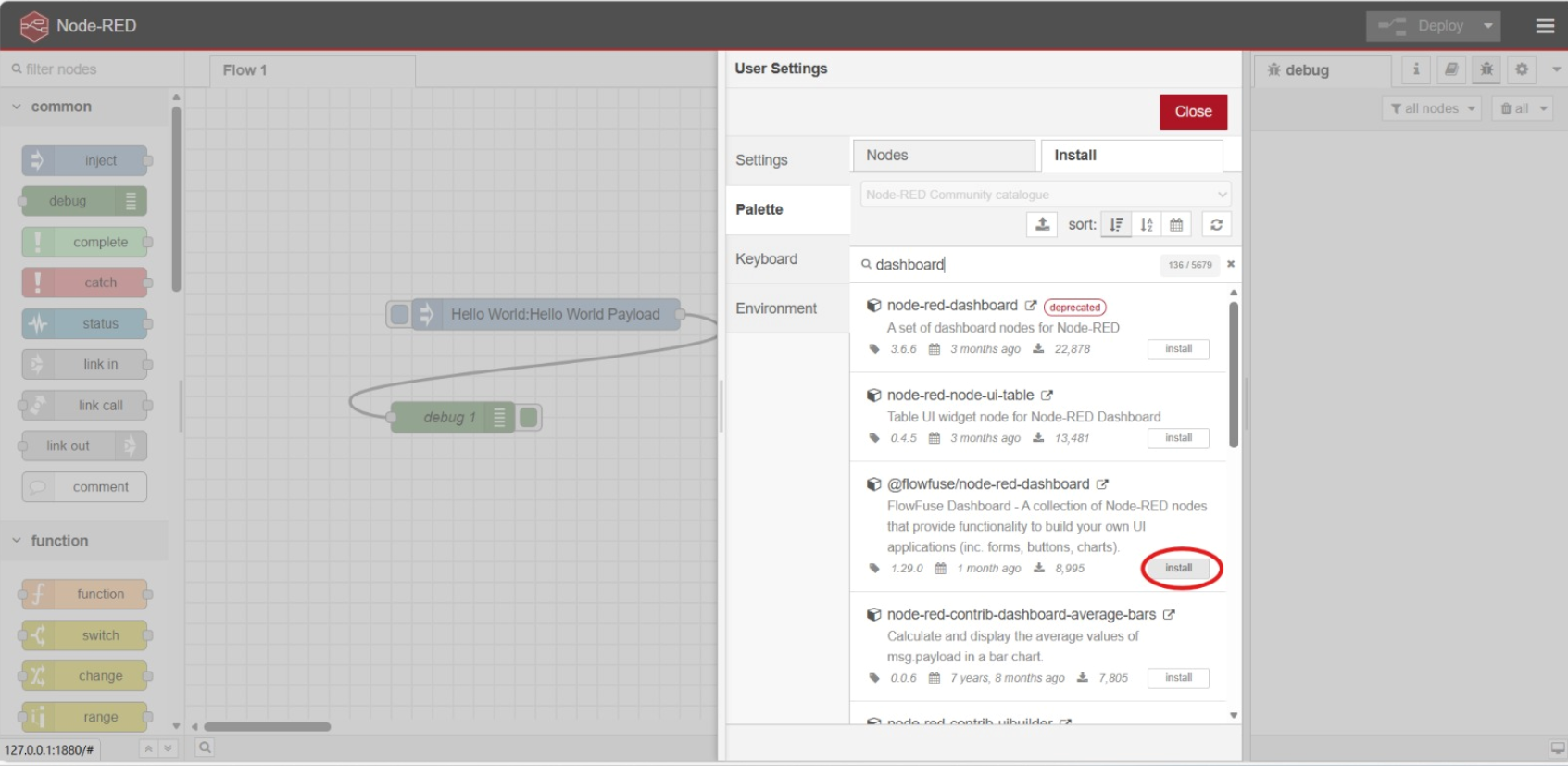
- You should now see the "Dashboard 2" node section if you scroll down enough. If you don't, then try to refresh the web or try to restart Node Red. Once you found it, drag the "button" node to the editor

- Double click the button node, then set the name to "LED", group to default (look at the screenshot below for reference), Label to "Toggle LED" and click the "Done" button once it is all finished

- Now scroll above in the node section till you found the
Functionnode section. Drag the "function" node to the editor and connect it with the "button" node that you've setup previously.

- Double click the "function" node and insert this code below, then click the "Done" button.
// Store LED state
context.ledState = context.ledState || false;
// Toggle LED state when button pressed
context.ledState = !context.ledState;
// Create message
msg.payload = {
led_state: context.ledState,
timestamp: new Date().toISOString(),
message: context.ledState ? "LED ON" : "LED OFF"
};
return msg;

Note: The code here is to simulate an LED, since we haven't integrate to Wokwi yet in this Tutorial.
- Go back to the
Dashboard 2section and drag the "Text Output" node in to the editor and connect it with the "function" node

- Double click the "Text Output" node then apply these configurations. Set name to "LED Status", set the group to default (see the screenshot below for reference), set the label to "LED Status:", make sure the value type is
msgand its value is "payload.message", and set the Layout the same as seen in the screenshot below. Click the "Done" button once eveything is finished.

9, Drag the "debug" node to the editor and connect it to the "function" node

- Click the dropdown icon in the top-right corner, then click on "Dashboard 2.0"

- Click on the setting of your default group

- Set the size to
3 x 1. You can change the value later on to experiment on the dashboard layout, but for now we keep it on3 x 1for simplicity. Click the "Update" button, once it is finished.

- Click the "Deploy" button so that the changes are reflected

- To check on the dashboard, click the "open dashboard" button

- You should be directed to a page similar to this. Try clicking on the "Toggle LED" button and see what happens.

- You can also see the log history in the debug section since you use the "debug" node

Node Red x Wokwi

- Double click the "Button Group" Node and apply this configuration

- Drag the "MQTT Out" Node to the editor

- Double click the "MQTT Out" node and add a MQTT server

- Apply this configuration and save the server

- Copy the remaining configuration for the "MQTT Out" node

Note: After this I added a "Debug" node that connects with the "Button Group" Node, but this is fully optional for you
- Drag the "MQTT In" node to the editor

- Double click the "MQTT IN" node and apply this configuration

- Drag the "Text Output" Node from the "Dashboard 2" Section and apply this configuration

- Create a new WOKWI ESP32 project and copy paste this code
#include <WiFi.h>
#include <PubSubClient.h>
// Wokwi WiFi - works in simulation
const char* ssid = "Wokwi-GUEST";
const char* password = "";
const char* mqtt_server = "test.mosquitto.org";
WiFiClient espClient;
PubSubClient client(espClient);
const int ledPin = 2;
bool ledState = false;
void setup_wifi() {
delay(10);
Serial.println("Connecting to WiFi...");
WiFi.begin(ssid, password);
while (WiFi.status() != WL_CONNECTED) {
delay(500);
Serial.print(".");
}
Serial.println("");
Serial.println("WiFi connected");
Serial.println("IP address: ");
Serial.println(WiFi.localIP());
}
void callback(char* topic, byte* message, unsigned int length) {
Serial.print("Message arrived on topic: ");
Serial.print(topic);
Serial.print(". Message: ");
String messageTemp;
for (int i = 0; i < length; i++) {
messageTemp += (char)message[i];
}
Serial.println(messageTemp);
// Check if message is for LED control
if (String(topic) == "wokwi/led/control") {
Serial.print("Changing LED to ");
if(messageTemp == "ON"){
digitalWrite(ledPin, HIGH);
ledState = true;
Serial.println("ON");
client.publish("wokwi/led/status", "ON");
}
else if(messageTemp == "OFF"){
digitalWrite(ledPin, LOW);
ledState = false;
Serial.println("OFF");
client.publish("wokwi/led/status", "OFF");
}
}
}
void reconnect() {
// Loop until we're reconnected
while (!client.connected()) {
Serial.print("Attempting MQTT connection...");
// Create a random client ID
String clientId = "WokwiClient-";
clientId += String(random(0xffff), HEX);
// Attempt to connect
if (client.connect(clientId.c_str())) {
Serial.println("connected");
// Subscribe to control topic
client.subscribe("wokwi/led/control");
// Publish connected message
client.publish("wokwi/led/status", "connected");
} else {
Serial.print("failed, rc=");
Serial.print(client.state());
Serial.println(" try again in 5 seconds");
delay(5000);
}
}
}
void setup() {
pinMode(ledPin, OUTPUT);
digitalWrite(ledPin, LOW);
Serial.begin(115200);
setup_wifi();
client.setServer(mqtt_server, 1883);
client.setCallback(callback);
}
void loop() {
if (!client.connected()) {
reconnect();
}
client.loop();
// Add a small delay
delay(100);
}
- Create the sketch where an LED is connected to PIN. The result should be similar to the following screenshot

- Add the
PubSubClientlibrary in the library manager

- Run the Wokwi simulation
Note: if you're having difficulties, you can follow this as a reference
- Deploy the Node Red project and go to the dashboard. You should be able to control the LED using the button there.


Module 10 - Mesh
10.1 Introduction
Module 10: Mesh
Learning Objectives
After completing this module, students are expected to be able to:
- Explain the concept, advantages, and basic architecture of IoT mesh networks.
- Implement a simple mesh network using ESP32 with the
painlessMeshlibrary. - Build a gateway (Root Node) to forward data from the mesh network to a server.
10.2 What is Mesh?
10.2.1 What is a Mesh Network?

A mesh network is a topology where each device (node) is interconnected, creating multiple paths for data. Unlike traditional networks that rely on a single central point (such as a router), a mesh network is decentralized.
How It Works
In a mesh network, each ESP32 node acts as both a sender and receiver, functioning as a repeater. This differs from a star network where communication only goes through one central hub. A mesh network is more decentralized, thus improving coverage and network reliability.
In this setup, one ESP32 acts as the root node, which connects the mesh network to an external network, while other nodes can serve as intermediate parents that forward data or as leaf nodes that only send and receive their own data. Data in the network is automatically routed through available nodes until it reaches the final destination, either another node within the mesh or an external network via the root node. This creates an efficient, flexible, and fault-tolerant network.
Key characteristics include:
- Self-Healing: If one node fails, data is automatically rerouted through another available path.
- Wide Coverage: Each node functions as a repeater, significantly extending signal range.
10.2.2 Topology Comparison: Mesh vs. Star
To understand the advantages, let’s compare it with the commonly used Star topology in home Wi-Fi.
-
Mesh

Connects devices directly, creating multiple paths for data. A mesh network is more flexible than a star network and requires fewer gateways to communicate with the same number of devices. However, it is more complex and costly compared to a star network. Mesh networks also lack universal standards, which may cause compatibility issues between devices from different vendors.
-
Star

Connects devices through a central hub. A star network is simpler and cheaper than a mesh network but depends heavily on the central hub. Device failures in a star network do not affect the rest of the system, but if the hub fails, the entire network goes down. Star networks are best suited for devices that need to communicate directly with a central node, such as office equipment, security cameras, and medical devices.
| Component | Mesh Topology | Star Topology |
|---|---|---|
| Resilience | Very High. Supports self-healing. | Low. If the hub/router fails, the entire network fails. |
| Coverage | Wide and flexible. Easy to expand. | Limited by the hub/router’s range. |
| Complexity | More complex to configure. | Simple and easy to set up. |
10.2.3 Types of Nodes in a Mesh Network
In this lab, we will learn about 4 types of nodes:
-
Root Node
The root node is the highest-level node in a Wi-Fi mesh network and acts as the only link between the mesh network and the external IP network. It connects directly to a conventional Wi-Fi router and forwards data packets between the external network and the mesh nodes. There must only be one root node in a mesh network, and it can only have one upstream connection—to the router. The root node is crucial in ensuring that all mesh network data can be accessed by external devices. -
Leaf Nodes
Leaf nodes are nodes that have no child nodes (no downstream connections). They can only send or receive their own data packets and do not forward data from other nodes. Typically, leaf nodes are located at the farthest edge of the mesh where no new downstream connections are possible. If a node only has a station interface (station-only node) and lacks a softAP interface, it is designated as a leaf node since downstream connections require a softAP. -
Intermediate Parent Nodes
Intermediate parent nodes are neither root nor leaf nodes. They have one upstream connection (to a parent node) and may have multiple downstream connections (to child nodes). These nodes can send, receive, and forward data from both upstream and downstream connections. Unlike leaf nodes, they can still form downstream connections in the future. They serve as bridges in the mesh network, enabling data to flow between different layers. -
Idle Nodes
Idle nodes are nodes that have not yet joined the mesh network. They attempt to establish an upstream connection with an existing intermediate parent node or try to become the root node if certain conditions are met (for example, when no root node exists in the network). Idle nodes remain passive until they successfully join or are integrated into the mesh network.
10.3 Example Code
10.3.1 Root Node
#include <Arduino.h>
#include <painlessMesh.h>
#include <WiFi.h>
// --- Konfigurasi Jaringan ---
#define MESH_PREFIX "jaringan_mesh_saya" // HARUS SAMA dengan semua node
#define MESH_PASSWORD "password_mesh" // HARUS SAMA dengan semua node
#define MESH_PORT 5555
painlessMesh mesh;
// Callback ketika Root menerima pesan dari Leaf
void receivedCallback(uint32_t from, String &msg) {
Serial.printf("Pesan diterima dari node %u: %s\n", from, msg.c_str());
}
void setup() {
Serial.begin(115200);
// Inisialisasi Mesh
mesh.setDebugMsgTypes(ERROR | STARTUP | CONNECTION);
mesh.init(MESH_PREFIX, MESH_PASSWORD, MESH_PORT);
// Set sebagai ROOT
mesh.setRoot(true);
mesh.setContainsRoot(true);
// Pasang callback untuk menerima pesan
mesh.onReceive(&receivedCallback);
Serial.println("Mesh dimulai sebagai ROOT");
Serial.print("Root ESP32 SoftAP IP: ");
Serial.println(WiFi.softAPIP());
}
void loop() {
mesh.update();
}
10.3.2 Leaf Node
#include <Arduino.h>
#include <painlessMesh.h>
// --- Konfigurasi Jaringan ---
#define MESH_PREFIX "jaringan_mesh_saya" // HARUS SAMA dengan semua node
#define MESH_PASSWORD "password_mesh" // HARUS SAMA dengan semua node
#define MESH_PORT 5555
painlessMesh mesh;
// Ganti sesuai nomor leaf
String leafName = "Leaf1";
void sendMessage() {
String msg = "Hello guys im " + leafName;
mesh.sendBroadcast(msg);
Serial.println("Sent: " + msg);
}
void setup() {
Serial.begin(115200);
mesh.setDebugMsgTypes(ERROR | STARTUP | CONNECTION);
mesh.init(MESH_PREFIX, MESH_PASSWORD, MESH_PORT);
}
void loop() {
mesh.update();
static unsigned long lastSend = 0;
if (millis() - lastSend > 5000) { // kirim tiap 5 detik
lastSend = millis();
sendMessage();
}
}
10.3.3 Intermediate Parent Node
#include <Arduino.h>
#include <painlessMesh.h>
// --- Konfigurasi Jaringan ---
#define MESH_PREFIX "jaringan_mesh_saya" // HARUS SAMA dengan semua node
#define MESH_PASSWORD "password_mesh" // HARUS SAMA dengan semua node
#define MESH_PORT 5555
painlessMesh mesh;
// Callback ketika node menerima pesan
void receivedCallback(uint32_t from, String &msg) {
Serial.printf("Pesan diterima dari %u: %s\n", from, msg.c_str());
// Intermediate node tidak perlu kirim ke server, cukup teruskan pesan
mesh.sendBroadcast(msg);
}
// Callback saat node terhubung
void newConnectionCallback(uint32_t nodeId) {
Serial.printf("Node baru terhubung: %u\n", nodeId);
}
// Callback saat node terputus
void changedConnectionCallback() {
Serial.println("Perubahan koneksi terjadi!");
}
// Callback saat node time sync
void nodeTimeAdjustedCallback(int32_t offset) {
Serial.printf("Waktu sinkronisasi, offset = %d\n", offset);
}
void setup() {
Serial.begin(115200);
// Inisialisasi mesh
mesh.setDebugMsgTypes(ERROR | STARTUP);
mesh.init(MESH_PREFIX, MESH_PASSWORD, &userScheduler, MESH_PORT);
// Callback
mesh.onReceive(&receivedCallback);
mesh.onNewConnection(&newConnectionCallback);
mesh.onChangedConnections(&changedConnectionCallback);
mesh.onNodeTimeAdjusted(&nodeTimeAdjustedCallback);
}
void loop() {
mesh.update();
}
10.3.4 Idle Node
There is no code because this is just a status if the node is not yet connected to the mesh.