Realtime System & IoT
- Tutorials
- Module 1: Introduction to RTOS & Task Scheduling
- Module 2: Memory Management & Queue
- Module 4 : Software Timers & Interrupts
- Module 5 : Deadlock & Multicore Systems
- Module 6 : Bluetooth
- Module 7 : WiFi, HTTP, and MQTT
- Module 8: IOT Platform (Blynk, Tuya)
- Module 9 : Mesh
- Modul 10: LoRa
Tutorials
PlatformIO (Recommended)
About
PlatformIO is a versatile, open-source ecosystem designed for embedded development, providing a unified platform for building, managing, and debugging firmware across a wide range of microcontroller architectures. Integrated with popular IDEs like VSCode and Atom, it offers powerful tools for code editing, dependency management, and cross-compilation. PlatformIO simplifies the development process with its rich library ecosystem, support for multiple frameworks, and seamless integration with version control systems, making it an invaluable tool for both hobbyists and professionals in the embedded systems community.
Install PlatformIO
1. Install VScode
If you haven't already, install VSCode on your machine. Download Here
2. Install PlatformIO Extension
After you've finished installing and setting up VSCode, open the Extensions menu, search for PlatformIO, and then install it.

Creating A New Project
1. Open the Projects & Configurations Tab
Open the PlatformIO menu. Then, within the Quick Access tab, select the Projects & Configurations tab.

2. Click Create New Project and Follow the Project Wizard
Click the Create New Project button, then fill out the required fields for the project.
First, set the name of the project.

Second, choose the board you want to use. In this example it will be DOIT ESP32 DEVKIT V1

Third, choose which framework you want to develop in. In this example, it will be the default choice, which is the Arduino framework.

(Optional) Uncheck the Use default location checkbox and choose the project location.

Lastly, click Finish
3. Open the Created Project
The project should be opened automatically, but if not, open it in the Projects & Configurations tab, similar to step 1.

Once the project is opened. Navigate to src/main.cpp file via the Explorer tab.

And done. This main.cpp file will be where you'll be coding your project, similar to a .ino file in the Arduino IDE.
Choosing Ports
By default, PlatformIO automatically chooses the correct port to upload your code to your board. Most of the time, it works. But if it doesn't work or maybe you have 2 or more boards connected, here's how you can choose the port of your active board.
1. Click the Port Button
Click the Set upload/monitor/test port button at the bottom.

2. Select an Active Port
Choose the port connected to your machine. Its most likely described as either CP210x or CH340.

Choosing a Project Environtment
If you have more that 1 project, you need to choose a default project so that PlatformIO knows which project are you currently working on.
1. Choose the Project Button
Click the Switch PlatformIO Project Environtment button at the bottom.

2. Choose a Project
Choose the project you want to work on. Utilize the search feature to ease your searching.

Uploading Code
Make sure that your port and project environtment is configured properly. Follow the steps above if you haven't done this already.
1. Click the Upload Button
Click the Upload Button

2. Hold the Boot Button on ESP32 if using an ESP32
Wait for your code to be compiled first. Then, when the connecting........ appears, hold the boot button on the ESP32 until the uploading process is complete.


Serial Monitor
1. Configure the Serial Baud Rate
monitor_speed = [Your baud rate]
Example :
monitor_speed = 115200

2. Click the Serial Monitor Button
Wait for the project to update, then click the Serial Monitor button.

Installing Libraries
You can install any library from PlatformIO.
1. Open the Libraries Page
Click the PlatformIO button, then open the Libraries Page

2. Search for a Library
Search for the Library you need

3. Add to Project
Click the Add to Project button. From this page, you can also view code examples, link to github repo, etc.

4. Choose Project
Choose the project you want to add the library. Then, click Add

5. Check the .ini File
Check if the lib_deps line is added. Save the file (Ctrl + S) if your file doesn't autosave.

6. Press the Build Button
Build the project so you can have code auto-completion.

7. Include the Project
Include the header file and you code auto-completion should work. Then, you can freely use the libary.


Module 1: Introduction to RTOS & Task Scheduling
Learning Objectives
- Understand the fundamentals of Real-Time Operating Systems (RTOS).
- Explore the basics of task scheduling and prioritization.
- Learn how to create and manage tasks using RTOS APIs.
- Understand the role of tick interrupts in task scheduling.
- Get introduced to basic task communication and synchronization mechanisms.
Module 1: Introduction to RTOS & Task Scheduling
Understanding Real-Time Operating Systems (RTOS)
A Real-Time Operating System (RTOS) is a type of operating system designed to meet the time constraints of real-time applications. Real-time applications are those that have strict time limits for completing their tasks, such as controlling robots, processing sensor data, or streaming audio/video. An RTOS ensures that real-time application tasks are executed predictably and deterministically, without being affected by other tasks or external events.
RTOS differs from general-purpose operating systems (GPOS) such as Windows, Linux, or macOS in several ways. GPOS are optimized for user experience and functionality rather than timing performance. GPOS can use complex algorithms and data structures to manage memory, files, processes, and resources, which can introduce variability and non-determinism in task execution times. GPOS may also perform background activities such as software updates, file indexing, or virus scanning, which can interfere with the primary tasks of real-time applications.
In contrast, RTOS is optimized for simplicity and efficiency rather than functionality and user experience. RTOS typically uses fixed-size memory blocks, static data structures, and pre-allocated resources to minimize overhead and latency. RTOS also avoids performing background activities unrelated to real-time applications. RTOS may sacrifice some common features and services found in GPOS, such as graphical user interfaces, file systems, networking, or security, to achieve better timing performance.
An RTOS generally consists of the following components:
- Kernel: The core of the operating system that manages tasks, interrupts, memory, and other resources.
- Scheduler: A part of the kernel that decides which task to run next based on their priorities and deadlines.
- Set of APIs: Functions that allow applications to interact with the operating system and access its services.
- Set of device drivers: Software modules that enable communication with hardware devices.
Importance of Task Scheduling in IoT
Task scheduling is one of the most important functions of an RTOS. Task scheduling is the process of deciding which task will be executed on the CPU at a given time. A task is a unit of work that performs a specific function in a real-time application. For example, a task might read data from a sensor, process an image, or send a message to another device.
Task scheduling is crucial in IoT (Internet of Things) applications, which involve numerous devices interacting with each other and their environment through sensors and actuators. IoT applications often have strict time constraints and require high reliability and responsiveness. For example, an IoT application might monitor temperature and humidity in a greenhouse and control the ventilation and irrigation systems accordingly. The application must ensure that sensor readings are accurate and timely, and that control actions are executed quickly and correctly.
Task scheduling in an RTOS aims to achieve two main objectives: feasibility and optimality. Feasibility means that all tasks can meet their deadlines without missing any. Optimality means that some performance criteria, such as CPU utilization, power consumption, or response time, are maximized or minimized. Achieving both objectives can be challenging, especially when there are many tasks with different priorities, periods, deadlines, execution times, and dependencies.
Task scheduling is the process of assigning tasks to processors and determining the order and timing of their execution. Task scheduling in IoT is important for the following reasons:
- Ensuring that tasks meet deadlines and quality of service requirements, such as latency, throughput, reliability, and energy efficiency.
- Optimizing the use of resources, such as CPU, memory, bandwidth, and power.
- Balancing the workload among multiple processors or cores, especially in multicore systems.
- Adapting to dynamic changes in the environment, such as workload variations, network conditions, or user preferences.
Types of Task Scheduling Algorithms
There are many types of task scheduling algorithms that can be used in an RTOS. Each algorithm has its advantages and disadvantages, depending on the characteristics of the tasks and the system. Some of the most common types of task scheduling algorithms are:
-
Run to Completion (RTC): The RTC scheduler is very simple. It runs one task until it completes, then stops it. After that, it runs the next task in the same way. This continues until all tasks have been run, then the sequence starts again. The simplicity of this scheme has the drawback that the allocation of time for each task is entirely influenced by the others. The system will not be very deterministic.
-
Round Robin (RR): The RR scheduler is similar to the RTC scheduler, except that a task does not need to finish its work before releasing the CPU. When rescheduled, it resumes from where it left off. The RR scheduler gives each task an equal share of CPU time in a circular order. This scheme is more flexible than RTC but still depends on the behavior of each task and does not hold the processor for too long.
-
Time Slice (TS): The TS scheduler is a type of preemptive scheduler that divides time into slots or ticks. Each slot might be 1 ms or less. At each tick interrupt, the scheduler selects one task to run from those ready to execute. The TS scheduler ensures that no task "starves" for CPU time but can introduce frequent context switches.
-
Fixed Priority (FP): The FP scheduler assigns each task a static priority level to indicate its relative urgency. The scheduler always selects the highest priority task from those ready to execute. If tasks with the highest priority have the same priority, they are executed in a round-robin fashion. If a higher priority task than the currently running task becomes ready, the higher priority task will immediately replace the lower priority task. The FP scheduler is widely used in real-time systems because it is simple and effective.
-
Earliest Deadline First (EDF): The EDF scheduler assigns each task a dynamic priority based on their deadlines. The scheduler always selects the task with the nearest deadline from those ready to execute. If two tasks have the same deadline, they are executed in a round-robin fashion. The EDF scheduler is optimal in the sense that it can schedule any feasible set of tasks. However, it can be difficult to implement and verify in practice.
Introduction to FreeRTOS
FreeRTOS is a widely-used open-source RTOS kernel in embedded systems, especially for IoT applications. FreeRTOS is designed to be simple, portable, and customizable. It supports various architectures, such as ARM, AVR, PIC, MSP430, and ESP32. It also supports various platforms, such as Arduino, Raspberry Pi, and AWS. FreeRTOS offers many features and services, such as:
-
Tasks: FreeRTOS allows the creation of multiple tasks that can run concurrently on one core or multiple cores. Each task has a priority level, stack size, and optional name. Tasks can be created, deleted, suspended, resumed, delayed, or synchronized using various API functions.
-
Queues: FreeRTOS provides queues for communication and synchronization between tasks. A queue is a data structure that can store a fixed number of items. Tasks can send and receive items to and from a queue using API functions. Queues can also be used to implement semaphores and mutexes.
-
Timers: FreeRTOS provides software timers for periodic or one-shot execution of callback functions. A timer is an object with a period, expiration time, and optional name. Timers can be created, deleted, started, stopped, or reset using API functions.
-
Event Groups: FreeRTOS provides event groups for signaling between tasks or between tasks and interrupts. An event group is a set of bits that can be set or cleared individually or collectively. Tasks can wait for one or more bits to be set in an event group using API functions.
-
Notifications: FreeRTOS provides notifications for lightweight and fast communication between tasks or between tasks and interrupts. A notification is a 32-bit value that can be sent to a task using API functions. Notifications can be used as binary or counting semaphores, mutexes, event flags, or data values.
ESP32: A Powerful Microcontroller for IoT
The ESP32 is a versatile, low-cost microcontroller with built-in WiFi and Bluetooth capabilities, making it ideal for IoT (Internet of Things) applications. Developed by Espressif Systems, it features a dual-core processor, allowing it to handle multiple tasks simultaneously. The ESP32 is equipped with a wide range of peripherals, including ADCs (Analog-to-Digital Converters), DACs (Digital-to-Analog Converters), GPIOs (General-Purpose Input/Outputs), PWM (Pulse Width Modulation), and more. It also supports various communication protocols, such as SPI, I2C, and UART, enabling seamless integration with other devices and sensors. With its power-efficient design, the ESP32 is well-suited for battery-powered projects, providing robust performance for real-time applications, wireless communication, and sensor data processing.
CP2102 vs. CH340: Differences in USB-to-Serial Converters
Both the CP2102 and CH340 are USB-to-serial converters commonly used in microcontroller development boards, including those based on the ESP32. They serve the same primary function of facilitating communication between the microcontroller and a computer via USB, but they differ in several key aspects:
-
Manufacturer:
- CP2102: Produced by Silicon Labs, the CP2102 is known for its stability and reliability. It’s a popular choice in higher-end development boards.
- CH340: Made by WCH (Nanjing QinHeng Corp), the CH340 is a more cost-effective alternative, commonly found in budget-friendly boards.
-
Driver Support:
- CP2102: Drivers for CP2102 are widely supported across various operating systems, including Windows, macOS, and Linux. The installation process is generally straightforward, with minimal compatibility issues.
- CH340: While also well-supported, CH340 drivers sometimes require manual installation, especially on macOS and Linux. In some cases, users may encounter more difficulties with initial setup compared to CP2102.
-
Performance:
- CP2102: Offers slightly better performance with higher data rates and lower latency, making it suitable for applications where speed and responsiveness are critical.
- CH340: While capable of handling most typical tasks, CH340 may exhibit slightly higher latency and lower maximum data rates compared to CP2102. However, it is usually sufficient for standard applications.
-
Cost:
- CP2102: Tends to be more expensive due to its advanced features and brand reputation.
- CH340: More affordable, which is why it is often found in low-cost development boards and devices.
In summary, the CP2102 is generally preferred for its robust performance and ease of use, especially in professional or high-demand scenarios. The CH340, on the other hand, is a budget-friendly option that is adequate for most hobbyist and educational purposes.
Setting Up FreeRTOS on ESP32
The ESP32 is an affordable, power-efficient microcontroller that supports WiFi and Bluetooth connectivity. It has two cores: the protocol core (CPU0) and the application core (CPU1). The protocol core runs wireless protocol stacks such as WiFi, Bluetooth, and BLE, while the application core runs user application code. Here’s how to install and configure the Arduino Core for ESP32:
-
Download and Install the Latest Version of the Arduino IDE:
- Download the latest version of the Arduino IDE from the Arduino website.
- Install the Arduino IDE following the provided instructions.
-
Configure the Arduino IDE for ESP32:
- Open the Arduino IDE.
- Navigate to
File>Preferences. - In the
Additional Boards Manager URLsfield, enter:https://dl.espressif.com/dl/package_esp32_index.json - Click
OK.
-
Install the ESP32 Board Package:
- Go to
Tools>Board>Boards Manager. - Search for
esp32. - Install the latest version of the
ESP32 by Espressif Systemspackage.
- Go to
-
Select Your ESP32 Board Model:
- Navigate to
Tools>Board>ESP32 Arduino. - Select your specific ESP32 board model (e.g.,
ESP32 Dev ModuleorESP32 Wrover Module).
- Navigate to
After completing these steps, your Arduino IDE will be set up to program the ESP32 using the FreeRTOS kernel. You can now start writing and uploading code to your ESP32 board.
Creating and Managing Tasks in FreeRTOS on ESP32
To create and manage tasks in FreeRTOS on the ESP32, you can use the following API functions:
-
xTaskCreate()
- This function creates a new task and dynamically allocates the required memory. It returns a handle to the created task or NULL if the task creation fails. The syntax of this function is:
BaseType_t xTaskCreate( TaskFunction_t pvTaskCode, const char * const pcName, const uint32_t usStackDepth, void * const pvParameters, UBaseType_t uxPriority, TaskHandle_t * const pvCreatedTask ); - Parameters:
-
pvTaskCode: A pointer to the function that implements the task. The function must have the prototype
void vTaskCode(void *pvParameters). - pcName: A descriptive name for the task, typically used for debugging purposes.
- usStackDepth: The number of words (not bytes) to allocate for the task's stack.
- pvParameters: A pointer to a variable that will be passed as a parameter to the task function.
- uxPriority: The priority at which the task will run. Higher numbers indicate higher priority.
- pvCreatedTask: A pointer to a variable that will receive the handle of the created task.
-
pvTaskCode: A pointer to the function that implements the task. The function must have the prototype
- Return values:
- pdPASS: The task was successfully created and added to the ready list.
- errCOULD_NOT_ALLOCATE_REQUIRED_MEMORY: The task could not be created due to insufficient available heap memory.
- This function creates a new task and dynamically allocates the required memory. It returns a handle to the created task or NULL if the task creation fails. The syntax of this function is:
-
xTaskCreatePinnedToCore()
- This function is similar to
xTaskCreate()but allows you to specify the core number on which the task will run. This can be useful for performance or affinity reasons. The syntax is:BaseType_t xTaskCreatePinnedToCore( TaskFunction_t pvTaskCode, const char * const pcName, const uint32_t usStackDepth, void * const pvParameters, UBaseType_t uxPriority, TaskHandle_t * const pvCreatedTask, const BaseType_t xCoreID ); - Parameters are the same as
xTaskCreate(), except:- xCoreID: The core number on which the task should run. This can be 0 or 1 for dual-core ESP targets or a valid core number for multi-core ESP targets.
- Return values are the same as
xTaskCreate().
- This function is similar to
-
vTaskDelete()
- This function deletes a task and frees the memory allocated by it. It can be used to delete the calling task or another task. The syntax is:
void vTaskDelete(TaskHandle_t xTask); - Parameters:
- xTask: The handle of the task to be deleted. Passing NULL will cause the calling task to be deleted.
- Return value: None.
- This function deletes a task and frees the memory allocated by it. It can be used to delete the calling task or another task. The syntax is:
-
vTaskDelay()
- This function blocks the calling task for a specified number of ticks (milliseconds). It can be used to implement periodic tasks. The syntax is:
void vTaskDelay(const TickType_t xTicksToDelay); - Parameters:
-
xTicksToDelay: The number of ticks to delay. One tick is a unit of time defined by the
configTICK_RATE_HZconstant inFreeRTOSConfig.h.
-
xTicksToDelay: The number of ticks to delay. One tick is a unit of time defined by the
- Return value: None.
- This function blocks the calling task for a specified number of ticks (milliseconds). It can be used to implement periodic tasks. The syntax is:
-
vTaskDelayUntil()
- This function blocks the calling task until a specific time, relative to the time when the function was last called. It can be used to implement tasks with a fixed frequency. The syntax is:
void vTaskDelayUntil(TickType_t * const pxPreviousWakeTime, const TickType_t xTimeIncrement); - Parameters:
- pxPreviousWakeTime: A pointer to a variable that stores the time when the task was last unblocked. This variable must be initialized with the current time before the first call to this function. The function will update the variable with the current time after each call.
-
xTimeIncrement: The cycle time period, in ticks. The task will be unblocked at times
(pxPreviousWakeTime + xTimeIncrement),(pxPreviousWakeTime + xTimeIncrement * 2), and so on.
- Return value: None.
- This function blocks the calling task until a specific time, relative to the time when the function was last called. It can be used to implement tasks with a fixed frequency. The syntax is:
-
vTaskSuspend()
- This function suspends a task, preventing it from being scheduled until it is resumed by another task. The syntax is:
void vTaskSuspend(TaskHandle_t xTaskToSuspend); - Parameters:
- xTaskToSuspend: The handle of the task to be suspended. Passing NULL will cause the calling task to be suspended.
- Return value: None.
- This function suspends a task, preventing it from being scheduled until it is resumed by another task. The syntax is:
-
vTaskResume()
- This function resumes a task that was suspended by
vTaskSuspend(). The syntax is:void vTaskResume(TaskHandle_t xTaskToResume); - Parameters:
- xTaskToResume: The handle of the task to be resumed.
- Return value: None.
- This function resumes a task that was suspended by
-
vTaskPrioritySet()
- This function changes the priority of a task. The syntax is:
void vTaskPrioritySet(TaskHandle_t xTask, UBaseType_t uxNewPriority); - Parameters:
- xTask: The handle of the task whose priority will be changed. Passing NULL will cause the priority of the calling task to be changed.
- uxNewPriority: The new priority for the task.
- Return value: None.
- This function changes the priority of a task. The syntax is:
-
uxTaskPriorityGet()
- This function returns the priority of a task. The syntax is:
UBaseType_t uxTaskPriorityGet(TaskHandle_t xTask); - Parameters:
- xTask: The handle of the task whose priority will be obtained. Passing NULL will cause the priority of the calling task to be returned.
- Return value:
- The priority of the specified task.
- This function returns the priority of a task. The syntax is:
-
eTaskGetState()
- This function returns the state of a task. The syntax is:
eTaskState eTaskGetState(TaskHandle_t xTask); - Parameters:
- xTask: The handle of the task whose state will be obtained.
- Return value:
- The possible states of the task are:
- eRunning: The task is currently running.
- eReady: The task is ready to run.
- eBlocked: The task is blocked, waiting for an event.
- eSuspended: The task is suspended.
- eDeleted: The task has been deleted.
- eInvalid: The task handle is invalid.
- The possible states of the task are:
- This function returns the state of a task. The syntax is:
Code Sample
/**
* FreeRTOS LED Demo
*
* One task flashes an LED at a rate specified by a value set in another task.
*
* Date: December 4, 2020
* Author: Shawn Hymel
* License: 0BSD
*/
// Needed for atoi()
#include <stdlib.h>
// Use only core 1 for demo purposes
#if CONFIG_FREERTOS_UNICORE
static const BaseType_t app_cpu = 0;
#else
static const BaseType_t app_cpu = 1;
#endif
// Settings
static const uint8_t buf_len = 20;
// Pins
static const int led_pin = LED_BUILTIN;
// Globals
static int led_delay = 500; // ms
//*****************************************************************************
// Tasks
// Task: Blink LED at rate set by global variable
void toggleLED(void *parameter)
{
while (1)
{
digitalWrite(led_pin, HIGH);
vTaskDelay(led_delay / portTICK_PERIOD_MS);
digitalWrite(led_pin, LOW);
vTaskDelay(led_delay / portTICK_PERIOD_MS);
}
}
// Task: Read from serial terminal
// Feel free to use Serial.readString() or Serial.parseInt(). I'm going to show
// it with atoi() in case you're doing this in a non-Arduino environment. You'd
// also need to replace Serial with your own UART code for non-Arduino.
void readSerial(void *parameters)
{
char c;
char buf[buf_len];
uint8_t idx = 0;
// Clear whole buffer
memset(buf, 0, buf_len);
// Loop forever
while (1)
{
// Read characters from serial
if (Serial.available() > 0)
{
c = Serial.read();
// Update delay variable and reset buffer if we get a newline character
if (c == '\n')
{
led_delay = atoi(buf);
Serial.print("Updated LED delay to: ");
Serial.println(led_delay);
memset(buf, 0, buf_len);
idx = 0;
}
else
{
// Only append if index is not over message limit
if (idx < buf_len - 1)
{
buf[idx] = c;
idx++;
}
}
}
}
}
//*****************************************************************************
// Main
void setup()
{
// Configure pin
pinMode(led_pin, OUTPUT);
// Configure serial and wait a second
Serial.begin(115200);
vTaskDelay(1000 / portTICK_PERIOD_MS);
Serial.println("Multi-task LED Demo");
Serial.println("Enter a number in milliseconds to change the LED delay.");
// Start blink task
xTaskCreatePinnedToCore( // Use xTaskCreate() in vanilla FreeRTOS
toggleLED, // Function to be called
"Toggle LED", // Name of task
1024, // Stack size (bytes in ESP32, words in FreeRTOS)
NULL, // Parameter to pass
1, // Task priority
NULL, // Task handle
app_cpu); // Run on one core for demo purposes (ESP32 only)
// Start serial read task
xTaskCreatePinnedToCore( // Use xTaskCreate() in vanilla FreeRTOS
readSerial, // Function to be called
"Read Serial", // Name of task
1024, // Stack size (bytes in ESP32, words in FreeRTOS)
NULL, // Parameter to pass
1, // Task priority (must be same to prevent lockup)
NULL, // Task handle
app_cpu); // Run on one core for demo purposes (ESP32 only)
// Delete "setup and loop" task
vTaskDelete(NULL);
}
void loop()
{
// Execution should never get here
}
Module 2: Memory Management & Queue
Learning Objective:
- Understand ESP32 Memory Structure
- Comprehend the Challenges of Memory Management
- Explore FreeRTOS Memory Management Techniques
- Implement Dynamic Memory Allocation
- Handle Memory Issues in Embedded Systems
- Understand Task Synchronization using Queues
Module 2: Memory Management & Queue
Memory Management in ESP32
Memory management is a crucial aspect of developing embedded systems, especially for platforms with limited resources like the ESP32. The ESP32 is a dual-core microcontroller that supports various wireless protocols, such as Wi-Fi, Bluetooth, and BLE. It has limited RAM (520 KB) and flash memory (4 MB), which must be utilized efficiently to run complex applications.
ESP32 manages memory resources using different memory regions and types. The main memory regions include:
- Internal Memory: This includes Instruction RAM (IRAM), Data RAM (DRAM), and Read-Only Memory (ROM). IRAM stores executable code, DRAM stores data and heap, and ROM holds boot code and some libraries.
- External Memory: This includes external SPI RAM (PSRAM) and flash memory. PSRAM can be used to extend DRAM, while flash memory can store application code and data through memory mapping.
The main types of memory are:
- Static Memory: Allocated at compile-time, with fixed size and location. This includes global and static variables, constants, and literals.
- Dynamic Memory: Allocated at runtime with flexible size and location. This includes local variables, heap, and stack.
One challenge with efficient memory use on the ESP32 is avoiding memory fragmentation, which occurs when available memory is split into small, non-contiguous blocks that cannot be used for allocation requests. Memory fragmentation can reduce system performance and stability, and even lead to memory allocation failures.
Another challenge is ensuring memory alignment with the CPU architecture's word size. The ESP32 uses a 32-bit architecture, meaning each word is 4 bytes. If memory access is not aligned with word boundaries, it can increase CPU cycles and cause bus errors.
FreeRTOS, the real-time operating system kernel, aids memory management on the ESP32 by providing:
- Multitasking scheduling, which allocates CPU time to tasks based on their priority and status. Each task has its own stack, which grows and shrinks dynamically based on the task's needs.
- Flexible memory allocation options, allowing developers to choose the most appropriate scheme for their applications. FreeRTOS provides five different heap implementations with varying complexity and features.
- Task synchronization primitives, such as queues, semaphores, mutexes, and event groups, which enable tasks to exchange data and coordinate their execution. These primitives are created with dynamic memory allocation from the FreeRTOS heap.
- A variety of APIs and mechanisms that facilitate memory management operations, such as creating and deleting tasks and queues, allocating and freeing heap memory, and querying available heap space.
Dynamic Memory Allocation and Deallocation
Dynamic memory allocation is the process of requesting and releasing memory at runtime. It allows developers to create data structures and objects whose size and lifetime are not known at compile-time. Dynamic memory allocation is useful in resource-constrained environments because it enables more efficient use of available memory.
FreeRTOS facilitates dynamic memory allocation and deallocation on the ESP32 by providing:
- A custom memory allocator that replaces the standard C
malloc()andfree()functions. The custom allocator uses a memory region called the FreeRTOS heap to allocate memory for tasks, queues, timers, semaphores, mutexes, event groups, software timers, etc. The size and location of the FreeRTOS heap are defined by the developer at compile-time. - A set of APIs that allow developers to allocate and free memory from the FreeRTOS heap. These APIs include:
-
pvPortMalloc() -
vPortFree() -
xPortGetFreeHeapSize() -
xPortGetMinimumEverFreeHeapSize()
-
These APIs are safe to use from tasks and Interrupt Service Routines (ISRs).
-
Five heap implementations with varying complexity and features:
- Heap_1: The simplest implementation, which does not support memory deallocation. It can only allocate memory until the heap is exhausted.
- Heap_2: Supports memory allocation and deallocation but does not attempt to coalesce adjacent free blocks into larger blocks. This can lead to memory fragmentation over time.
-
Heap_3: Simply wraps the standard C
malloc()andfree()functions, relying on the system heap defined by the compiler, which may not be suitable for real-time applications. - Heap_4: The recommended implementation, which supports memory allocation and deallocation, and coalesces adjacent free blocks into larger blocks. It uses a linked list to manage heap blocks and critical sections to protect the list from concurrent access.
- Heap_5: Similar to Heap_4 but allows adding multiple non-contiguous memory regions to the heap. This is useful for platforms with memory scattered across different locations.
Developers can choose the desired heap implementation by including the appropriate header file in their project, such as heap_1.c, heap_2.c, etc.
Potential Issues and Considerations for Dynamic Memory Allocation
Dynamic memory allocation in FreeRTOS has several potential issues and considerations for developers:
- Memory Leaks: Occur when dynamically allocated memory blocks are not freed after they are no longer needed. This can reduce the available heap space and eventually lead to memory allocation failures. To avoid memory leaks, developers should always free allocated memory blocks and use heap monitoring tools to detect and debug memory leaks.
- Memory Corruption: Occurs when a memory block is accessed or modified after it has been freed, or when a memory block is overwritten by another block. This can cause unexpected behavior and system crashes. To avoid memory corruption, developers should follow good programming practices, such as using pointers carefully, checking the return values of memory allocation functions, and avoiding buffer overflows.
-
Memory Alignment: Refers to the requirement that memory access must be aligned with the CPU architecture's word size. As mentioned earlier, the ESP32 uses a 32-bit architecture, meaning each word is 4 bytes. If memory access is not aligned with word boundaries, it can increase CPU cycles and cause bus errors. To ensure memory alignment, FreeRTOS aligns all heap blocks to 8-byte boundaries by default. Developers can also use the
portBYTE_ALIGNMENTmacro to specify a different alignment value.
Understanding Memory Fragmentation
Memory fragmentation is a phenomenon where available memory is divided into small, non-contiguous blocks that cannot be used for allocation requests. Memory fragmentation can degrade system performance and stability and even lead to memory allocation failures. Memory fragmentation can be classified into two types: internal and external.
-
Internal Fragmentation: This occurs when the memory block is larger than the requested size, and the excess space is wasted. For example, if a 16-byte block is allocated for a 10-byte request, 6 bytes are wasted internally. Internal fragmentation can be reduced by using smaller block sizes or combining multiple objects into a single block.
-
External Fragmentation: This happens when gaps between allocated blocks are too small to satisfy any allocation requests. For instance, if there are three free blocks of 4 bytes, 8 bytes, and 12 bytes, none of them can fulfill a 16-byte request. External fragmentation can be minimized by merging adjacent free blocks into a larger one or using compaction techniques to move allocated blocks and eliminate gaps.
Memory fragmentation can occur in both static and dynamic memory allocation, but it is more common and problematic in dynamic memory allocation. This is because dynamic memory allocation involves frequent requests and releases of variable-sized blocks, creating an irregular pattern of free and used spaces in the heap.
In the context of ESP32 and FreeRTOS, memory fragmentation can happen due to several factors, such as:
-
Use of Different Memory Regions and Types: ESP32 uses different memory regions (internal and external) and memory types (static and dynamic) to manage its limited RAM and flash resources. These regions and types have different characteristics and constraints that affect their fragmentation levels. For example, internal DRAM has faster access speed but a smaller size than external PSRAM; static memory has fixed size and location but doesn’t experience fragmentation, while dynamic memory has variable size and location but is prone to fragmentation.
-
Heap Implementation Choices: FreeRTOS provides five different heap implementations that vary in complexity and features. These implementations have different impacts on the internal and external fragmentation levels in the FreeRTOS heap. For example, Heap_1 has no external fragmentation but suffers from high internal fragmentation; Heap_2 has low internal fragmentation but high external fragmentation; Heap_3 has variable fragmentation depending on the system heap; Heap_4 and Heap_5 have low internal and external fragmentation by combining free blocks.
-
Memory Allocation and Deallocation Patterns: The way tasks allocate and free memory from the FreeRTOS heap can affect fragmentation levels. For example, if tasks allocate and release memory randomly and unpredictably, it can create more gaps and irregularities in the heap. Conversely, if tasks allocate and release memory consistently and regularly, it can create more continuous and uniform blocks in the heap.
Introduction to Queues in FreeRTOS
Queues are one of the inter-task coordination primitives provided by FreeRTOS. A queue is a data structure that holds several items of the same type in a first-in, first-out (FIFO) order. Queues are useful for multitasking applications as they allow tasks to exchange data and synchronize their execution.
The basic concepts of a queue are:
-
Structure: A queue consists of two parts: the control block and the storage area. The control block contains information about the queue, such as its name, size, item size, the number of items, pointers to the head and tail of the queue, etc. The storage area is a byte array that holds the actual items in the queue. The size of the storage area is determined by multiplying the item size by the queue length.
-
Purpose: Queues have two main purposes: data transfer and task synchronization. Data transfer refers to the process of sending and receiving data between tasks using a queue. Task synchronization refers to the process of blocking and unblocking tasks based on the availability of data in the queue.
-
Benefits: Queues offer several benefits for multitasking applications, such as:
-
Decoupling: Queues decouple the sending and receiving tasks, meaning they do not need to know each other’s identity, priority, or status. They only need to know the queue name they use to communicate.
-
Buffering: Queues store data between the sending and receiving tasks, meaning they do not need to be synchronized in time. The sender can send data at any time, and the receiver can receive data at any time, as long as there is space or data in the queue.
-
Scalability: Queues can easily scale to support multiple sending and receiving tasks, meaning they can handle simultaneous and varying data flows. Several tasks can share the same queue to send or receive data.
-
Queue Implementation for Task Communication
To implement queues in FreeRTOS for the ESP32, follow these steps:
-
Creating a Queue:
A queue can be created using thexQueueCreate()API function. This function takes two parameters: the queue length (the number of items it can hold) and the size of each item (the number of bytes per item). It returns a handle for the created queue, orNULLif creation fails. For example:// Create a queue that can hold 10 items, each 4 bytes in size QueueHandle_t xQueue = xQueueCreate(10, sizeof(uint32_t)); -
Sending Data to the Queue:
Data can be sent to a queue using thexQueueSend()orxQueueSendFromISR()API functions. These functions take three parameters: the queue handle, a pointer to the data to be sent, and a timeout value (the number of ticks to wait if the queue is full). These functions returnpdTRUEif data is successfully sent orpdFALSEif the timeout expires or an error occurs. UsexQueueSend()from a task, andxQueueSendFromISR()from an ISR. For example:// Send the value 100 to the queue from a task uint32_t ulValueToSend = 100; BaseType_t xStatus = xQueueSend(xQueue, &ulValueToSend, 0); // Send the value 200 to the queue from an ISR uint32_t ulValueToSend = 200; BaseType_t xStatus = xQueueSendFromISR(xQueue, &ulValueToSend, NULL); -
Receiving Data from the Queue:
Data can be received from a queue using thexQueueReceive()orxQueueReceiveFromISR()API functions. These functions take three parameters: the queue handle, a pointer to the variable where the received data will be stored, and a timeout value (the number of ticks to wait if the queue is empty). These functions returnpdTRUEif data is successfully received orpdFALSEif the timeout expires or an error occurs. For example:// Receive a value from the queue into a variable from a task uint32_t ulReceivedValue; BaseType_t xStatus = xQueueReceive(xQueue, &ulReceivedValue, portMAX_DELAY); // Receive a value from the queue into a variable from an ISR uint32_t ulReceivedValue; BaseType_t xStatus = xQueueReceiveFromISR(xQueue, &ulReceivedValue, NULL); -
Deleting a Queue:
A queue can be deleted using thevQueueDelete()API function. This function takes one parameter: the queue handle to be deleted. It frees the memory allocated for the queue and removes it from kernel control. For example:// Delete the queue vQueueDelete(xQueue);
Common Use Cases for Queues in Task Communication
Queues are crucial for effective task communication in various practical use cases, such as:
-
Producer-Consumer: A common pattern where one or more tasks produce data and send it to a queue, and one or more tasks consume data by receiving it from the queue. For example, a sensor task could read data from a sensor and send it to a queue, while a display task could receive the data and show it on an LCD screen.
-
Command and Response: Another common pattern where one task sends commands to another task through a queue, and the other task sends responses back through a separate queue. For instance, a user interface task might send commands to a motor control task via a queue, and the motor control task could send status updates back through another queue.
Queue Synchronization and Data Transfer
Queue synchronization refers to the process of blocking and unblocking tasks based on the availability of data in the queue. This synchronization allows tasks to wait for data to be sent or received without wasting CPU time.
Queue synchronization mechanisms include:
-
Blocking: When a task tries to send or receive data from a full or empty queue, respectively. The task enters the Blocked state and waits until there is space or data in the queue or until the timeout expires. The task is removed from the Ready list and placed in the Blocked list associated with that queue.
-
Unblocking: When a blocked task in a queue is able to send or receive data. The task exits the Blocked state and returns to the Ready state. It is removed from the Blocked list and placed in the Ready list based on its priority.
-
Preemption: When a blocked task in a queue has a higher priority than the currently running task. The currently running task is preempted and placed in the Ready list, and the blocked task is chosen for execution by the scheduler.
-
Yielding: When a blocked task in a queue has the same priority as the currently running task. The running task voluntarily gives up the CPU to the blocked task by calling the
taskYIELD()API function. The running task remains in the Ready list but yields the rest of its time slice.
Queue data transfer refers to the process of sending and receiving data between tasks using a queue. This allows tasks to exchange information and coordinate their actions effectively.
Code Sample
This example demonstrates a simple FreeRTOS queue communication between two tasks (Task1 and Task2) running on an ESP32. Here's how it works:
-
Task1: This task generates a random integer between 0 and 100, dynamically allocates memory for it usingpvPortMalloc(), and attempts to send the pointer to the integer to a queue (xQueue). If the queue is full and the message cannot be sent, it prints an error message and frees the allocated memory. After each send attempt, the task delays for 1 second. -
Task2: This task waits to receive data from the queue. When a message is received, it prints the received value and then frees the memory used for the integer. -
setup(): Initializes the serial communication, creates the queue, and starts the two tasks (Task1andTask2) pinned to core 1. If the queue creation fails, it prints an error message. -
loop(): The main Arduino loop remains empty since the tasks are running independently of it.
Here’s the full code:
QueueHandle_t xQueue;
void Task1(void *pvParameters) {
int *p;
while (1) {
// Dynamically allocate memory for an integer
p = (int *)pvPortMalloc(sizeof(int));
*p = random(0, 100); // Generate a random number between 0 and 100
// Attempt to send the pointer to the queue, wait indefinitely if needed
if (xQueueSend(xQueue, &p, portMAX_DELAY) != pdPASS) {
Serial.println("Failed to post to queue");
vPortFree(p); // Free memory if message could not be sent to the queue
}
vTaskDelay(1000 / portTICK_PERIOD_MS); // Delay for 1 second
}
}
void Task2(void *pvParameters) {
int *p;
while (1) {
// Wait to receive a pointer from the queue, wait indefinitely if needed
if (xQueueReceive(xQueue, &p, portMAX_DELAY)) {
Serial.print("Received: ");
Serial.println(*p); // Print the received value
vPortFree(p); // Free memory after processing
}
}
}
void setup() {
Serial.begin(115200);
// Create a queue capable of holding 10 integer pointers
xQueue = xQueueCreate(10, sizeof(int *));
if (xQueue == NULL) {
Serial.println("Error creating the queue");
}
// Create two tasks pinned to core 1
xTaskCreatePinnedToCore(Task1, "Task1", 10000, NULL, 1, NULL, 1);
xTaskCreatePinnedToCore(Task2, "Task2", 10000, NULL, 1, NULL, 1);
vTaskDelete(NULL); // Delete the setup task to free memory
}
void loop() {
// Empty loop since tasks are handled in FreeRTOS tasks
}
Key Points:
- Dynamic Memory Allocation: Each task dynamically allocates memory for the integer it sends, and the receiving task is responsible for freeing that memory after use.
- Queue: A queue is created to hold pointers to integers. Both tasks communicate through this queue.
- Core Assignment: The tasks are pinned to core 1 for performance reasons, but this can be changed based on requirements.
Module 4 : Software Timers & Interrupts
Module 4 : Software Timers & Interrupts
Software Timer
Software timer is a feature of FreeRTOS that can call a function when the timer expires. This function is known as a callback function and is passed to the timer as an argument. The callback function must be quick and non-blocking, similar to an ISR.
Software timers rely on a tick timer, which is a hardware timer that generates interrupts at a fixed frequency. The tick timer determines the resolution of the software timer, meaning that we cannot create a software timer with a period or delay of less than one tick.
There are two types of software timers: one-shot and auto-reload. A one-shot timer will run the callback function only once after the specified delay. An auto-reload timer will run the callback function repeatedly at the specified period.
How to Use Software Timer
To use a software timer in FreeRTOS (the vanilla version, not the one currently in use), we need to include the header file timers.h, which contains API functions for creating, deleting, starting, stopping, and resetting the timer. We also need to enable the configUSE_TIMERS setting in the FreeRTOSConfig.h file, which will create a background task that manages the software timers.
This background task is called the timer service task or timer daemon. It maintains a list of timers and calls their callback functions when the timers expire. This task does not run continuously but wakes up only when the tick timer reaches one of the expiration times.
We do not control the timer service task directly, but instead, we send commands to it via a queue. The queue is accessed by the API functions, which place commands in the queue to create, start, stop, and reset timers.
The API functions return a boolean value indicating whether the command was successfully sent to the queue or not. If the queue is full, we can specify a timeout value to wait for space to become available in the queue.
How to Create a Software Timer
To create a software timer, we use the xTimerCreate function, which returns a handle to the timer. This handle is used to identify and control the timer in other API functions.
The xTimerCreate function takes five parameters:
- Timer name, which is a string for debugging purposes.
-
Timer period or delay, in ticks. We can use the macro
pdMS_TO_TICKSto convert milliseconds to ticks. -
Auto-reload setting, which can be
pdTRUEfor an auto-reload timer orpdFALSEfor a one-shot timer. - Timer ID, which is a pointer to any data type. We can use it to store some information about the timer or to identify it in the callback function.
- Callback function, which is the name of the function to be called when the timer expires.
For example, we can create a one-shot timer that will call a function named vOneShotCallback after 2000 milliseconds with the following code:
TimerHandle_t xOneShotTimer;
xOneShotTimer = xTimerCreate("OneShot", pdMS_TO_TICKS(2000), pdFALSE, (void *) 0, vOneShotCallback);
We can create an auto-reload timer that will call the vAutoReloadCallback function every 1000 milliseconds with the following code:
TimerHandle_t xAutoReloadTimer;
xAutoReloadTimer = xTimerCreate("AutoReload", pdMS_TO_TICKS(1000), pdTRUE, (void *) 1, vAutoReloadCallback);
Note that we have used different values for the timer ID parameter to distinguish between the two timers.
We should always check whether the xTimerCreate function returns a valid handle or not. If it returns NULL, it means that there is not enough heap memory allocated for the timer.
How to Start a Software Timer
To start a software timer, we use the xTimerStart function, which takes two parameters:
- Timer handle that will be started.
- Timeout value to send the command to the queue.
For example, we can start a one-shot timer and an auto-reload timer with the following code:
if (xOneShotTimer != NULL) {
xTimerStart(xOneShotTimer, portMAX_DELAY);
}
if (xAutoReloadTimer != NULL) {
xTimerStart(xAutoReloadTimer, portMAX_DELAY);
}
We have used portMAX_DELAY as the timeout value, which means we will wait indefinitely if the queue is full.
Note that the xTimerStart function will also restart the timer if it is already running. This means the timer will be reset to its initial value.
How to Stop a Software Timer
To stop a software timer, use the following code:
if (xAutoReloadTimer != NULL) { xTimerStop(xAutoReloadTimer, portMAX_DELAY); }
How to Reset a Software Timer
To reset a software timer, use the following code:
if (xOneShotTimer != NULL) { xTimerReset(xOneShotTimer, portMAX_DELAY); }
How to Delete a Software Timer
To delete a software timer, use the following code:
if (xOneShotTimer != NULL) { xTimerDelete(xOneShotTimer, portMAX_DELAY); }
if (xAutoReloadTimer != NULL) { xTimerDelete(xAutoReloadTimer, portMAX_DELAY); }
How to Create a Callback Function
A callback function is a function given to the timer as an argument and called when the timer expires. This function should not return anything and should take the timer handle as a parameter.
We can use the timer handle to identify which timer called the function or to access the ID or other information. We can also use the xTimerChangePeriod function to change the period of a running timer from within the callback function.
We should write our callback function in a manner similar to an ISR: it should be quick and non-blocking, avoiding the use of delay functions or blocking operations with queues, mutexes, and semaphores. The callback function should avoid calling API functions that are not interrupt-safe.
For example, we can write one-shot and auto-reload callback functions with the following code:
void vOneShotCallback(TimerHandle_t xTimer) { // Get the timer ID
uint32_t ulTimerID = (uint32_t) pvTimerGetTimerID(xTimer);
// Check if it is our one-shot timer
if (ulTimerID == 0) {
// Do something once
Serial.println("One-shot timer expired");
}
}
void vAutoReloadCallback(TimerHandle_t xTimer) { // Get the timer ID
uint32_t ulTimerID = (uint32_t) pvTimerGetTimerID(xTimer);
// Check if it is our auto-reload timer
if (ulTimerID == 1) {
// Do something repeatedly
Serial.println("Auto-reload timer expired");
}
}
Real-Time Operating System (RTOS) and Hardware Interrupts
A Real-Time Operating System (RTOS) is a software platform that allows embedded systems to run multiple tasks concurrently and efficiently. One of the key features of an RTOS is the ability to handle hardware interrupts, which are signals that notify the processor of asynchronous events requiring immediate attention.
Hardware interrupts can be generated by various sources, such as timers, buttons, communication buses, or sensors. For example, a timer can trigger an interrupt when it reaches a certain count, or a button can trigger an interrupt when pressed by the user. These interrupts can be used to perform specific actions or gather data from devices.
However, hardware interrupts also pose several challenges for RTOS developers. For instance, how to synchronize shared data and variables between interrupt service routines (ISRs) and tasks? How to avoid blocking or delaying other interrupts or tasks when processing an interrupt? How to use RTOS API functions correctly and safely within an ISR?
Setting Up Hardware Interrupts
Let's start with a simple example of setting up a hardware timer interrupt on the ESP32. The ESP32 has four timers, each with a 16-bit prescaler and a 64-bit counter. The default timer base clock is 80 MHz, which means the timer ticks 80 million times per second.
We can use a prescaler to reduce the timer frequency. For example, if we set the prescaler to 80, the timer will tick at 1 MHz, or one million times per second. We can also set a maximum count value for the timer, which determines when the timer will trigger an interrupt. For instance, if we set the maximum count to one million, the timer will trigger an interrupt every second.
We can use the ESP32 HAL timer library included with the Arduino package to configure and start the timer. We also need to define an ISR function that will execute when the timer interrupt occurs. In this example, we will simply toggle an LED within the ISR.
Code to Set Up Timer Interrupt
// Define LED pin
#define LED_PIN 2
// Define timer handle
hw_timer_t *timer = NULL;
// Define ISR function
void IRAM_ATTR onTimer() {
// Toggle LED
digitalWrite(LED_PIN, !digitalRead(LED_PIN));
}
void setup() {
// Configure LED pin as output
pinMode(LED_PIN, OUTPUT);
// Create and start hardware timer number 0
timer = timerBegin(0, 80, true);
// Configure ISR as a callback function
timerAttachInterrupt(timer, &onTimer, true);
// Set maximum count value
timerAlarmWrite(timer, 1000000, true);
// Enable timer interrupt
timerAlarmEnable(timer);
}
void loop() {
// Do nothing
}
Timer Interrupt and Synchronizing Variables between ISRs and Tasks
If we upload this code to an ESP32 board, we should see the LED blinking with a one-second interval.
Synchronizing Variables between ISRs and Tasks
A common scenario in embedded systems is to collect data from a device using an ISR and then process that data in a task. For example, we might want to sample an analog value from a sensor at a regular interval using a timer interrupt, and then compute some statistics or perform calculations on that value in a task.
However, this also means we need to share some variables between the ISR and the task. For instance, we may need to store the sampled values in a global variable or buffer that can be accessed by both the ISR and the task. This introduces some challenges for synchronization and concurrency control.
One of the main challenges is that an ISR can interrupt a task at any time and modify shared variables while the task is using them. This can result in inconsistent or corrupted data. For example, consider a global variable storing an integer value. The ISR increments this variable by one every time it runs. The task decrements this variable by one in a loop and prints its value.
If we don't synchronize this variable properly, we might encounter issues. For instance, if the initial value of the variable is zero. The task reads this value and prepares to decrement it by one. However, before it can write the new value of negative one, an ISR occurs and increments the variable by one. The ISR finishes and returns to the task. The task then writes back its computed value, negative one, overwriting the one that was just set by the ISR. The result is incorrect, negative one instead of zero.
To avoid such issues, we need to protect the shared variable from being accessed simultaneously by both the ISR and the task. One way to do this is by using critical sections. A critical section is a code segment that disables interrupts and prevents context switching while it is executing. This ensures that the shared variable is accessed by only one entity at a time.
In FreeRTOS, we can use special functions to enter and exit critical sections. For example, we can use taskENTER_CRITICAL() and taskEXIT_CRITICAL() in tasks, and portENTER_CRITICAL_ISR() and portEXIT_CRITICAL_ISR() in ISRs. These functions also use spinlocks to prevent tasks on other cores from entering the critical section.
Here is an example of using critical sections to protect shared variables between an ISR and a task:
Code for Synchronizing Variables between ISRs and Tasks
// Define LED pin
#define LED_PIN 2
// Define timer handle
hw_timer_t *timer = NULL;
// Define global variable
volatile int counter = 0;
// Define ISR function
void IRAM_ATTR onTimer() {
// Enter critical section
portENTER_CRITICAL_ISR(&timerMux);
// Increment global variable
counter++;
// Exit critical section
portEXIT_CRITICAL_ISR(&timerMux);
}
// Define task function
void printValues(void * parameter) {
// Loop forever
while (true) {
// Enter critical section
taskENTER_CRITICAL();
// Decrement global variable
counter--;
// Exit critical section
taskEXIT_CRITICAL();
// Print global variable
Serial.println(counter);
// Wait for two seconds
delay(2000);
}
}
void setup() {
// Start serial terminal
Serial.begin(115200);
// Configure LED pin as output
pinMode(LED_PIN, OUTPUT);
// Create and start hardware timer number 0
timer = timerBegin(0, 8, true);
// Configure ISR as a callback function
timerAttachInterrupt(timer, &onTimer, true);
// Set maximum count value
timerAlarmWrite(timer, 100000, true);
// Enable timer interrupt
timerAlarmEnable(timer);
// Create and start task
xTaskCreatePinnedToCore(printValues, "Print Values", 10000, NULL, 1, NULL, app_cpu);
}
void loop() {
// Do nothing
}
If we upload this code to our ESP32 board, we should see the global variable counting down from some value every two seconds. We may also observe some repeated values, indicating that the ISR is running between the serial print statements. This behavior is expected, as we want the ISR to run asynchronously and separately from the task.
Using Semaphores for Synchronizing ISR and Tasks
Another way to synchronize an ISR and a task is by using semaphores. A semaphore is a signaling mechanism that can be used to control access to shared resources or to notify a task about an event. Semaphores can have binary or counting values. A binary semaphore can only have two states: available or taken. A counting semaphore can have multiple states: from zero to a maximum value.
Semaphores can be taken or given by tasks or ISRs. Taking a semaphore means acquiring or locking the semaphore. Giving a semaphore means releasing or unlocking it. A task can be blocked on a semaphore until it becomes available. An ISR cannot be blocked on a semaphore but can give a semaphore to unlock a waiting task.
One common use case for a semaphore is to signal a task when some data is ready to be processed by an ISR. For example, we might want to sample analog values from different sensors at a regular interval using a timer interrupt and then compute some statistics or perform calculations on those values in a task.
In this case, we can use a binary semaphore to notify the task when the ISR has sampled new values. The ISR will store the sampled values in a global variable and give the semaphore. The task will wait on the semaphore and take it when available. The task will then read the global variable and process the sampled values.
However, we need to use special functions ending with FromISR when using semaphores within an ISR. These functions will never block and will also check if giving the semaphore has unlocked a higher-priority task. If so, they will request a context switch so that the higher-priority task can run immediately after the ISR finishes.
Here is an example of using a binary semaphore to synchronize an ISR and a task:
// Define global variables
SemaphoreHandle_t binarySemaphore;
volatile int sampledValue = 0;
// Define ISR function
void IRAM_ATTR onTimer() {
// Store sampled value
sampledValue = analogRead(A0);
// Give semaphore
xSemaphoreGiveFromISR(binarySemaphore, NULL);
}
// Define task function
void processValues(void * parameter) {
while (true) {
// Wait for semaphore
if (xSemaphoreTake(binarySemaphore, portMAX_DELAY) == pdTRUE) {
// Process sampled value
Serial.println(sampledValue);
}
}
}
void setup() {
// Start serial terminal
Serial.begin(115200);
// Create binary semaphore
binarySemaphore = xSemaphoreCreateBinary();
// Create and start hardware timer
timer = timerBegin(0, 80, true);
timerAttachInterrupt(timer, &onTimer, true);
timerAlarmWrite(timer, 1000000, true);
timerAlarmEnable(timer);
// Create and start task
xTaskCreatePinnedToCore(processValues, "Process Values", 10000, NULL, 1, NULL, app_cpu);
}
void loop() {
// Do nothing
}
In this example, the ISR samples a value and gives the semaphore. The task waits for the semaphore, takes it when available, and processes the sampled value.
Using Semaphores for Synchronizing ISR and Tasks
Another way to synchronize an ISR and a task is by using semaphores. A semaphore is a signaling mechanism that can be used to control access to shared resources or notify a task about an event. Semaphores can have binary or counting values. A binary semaphore can only have two states: available or taken. A counting semaphore can have multiple states: from zero to a maximum value.
Semaphores can be taken or given by tasks or ISRs. Taking a semaphore means acquiring or locking the semaphore. Giving a semaphore means releasing or unlocking it. A task can be blocked on a semaphore until it becomes available. An ISR cannot be blocked on a semaphore but can give a semaphore to unlock a waiting task.
One common use case for a semaphore is to signal a task when some data is ready to be processed by an ISR. For example, we might want to sample analog values from different sensors at a regular interval using a timer interrupt and then compute some statistics or perform calculations on those values in a task.
In this case, we can use a binary semaphore to notify the task when the ISR has sampled new values. The ISR will store the sampled values in a global variable and give the semaphore. The task will wait on the semaphore and take it when available. The task will then read the global variable and process the sampled values.
However, we need to use special functions ending with FromISR when using semaphores within an ISR. These functions will never block and will also check if giving the semaphore has unlocked a higher-priority task. If so, they will request a context switch so that the higher-priority task can run immediately after the ISR finishes.
Here is an example of using a binary semaphore to synchronize an ISR and a task:
// Define LED pin
#define LED_PIN 2
// Define timer handler
hw_timer_t *timer = NULL;
// Define global variable
volatile int adcValue = 0;
// Define binary semaphore
SemaphoreHandle_t binSemaphore = NULL;
// Define ISR function
void IRAM_ATTR onTimer() {
// Sample analog value from pin 34
adcValue = analogRead(34);
// Give binary semaphore
xSemaphoreGiveFromISR(binSemaphore, NULL);
}
// Define task function
void processValues(void * parameter) {
// Loop forever
while (true) {
// Wait for binary semaphore
xSemaphoreTake(binSemaphore, portMAX_DELAY);
// Process the sampled value
Serial.println(adcValue);
// Wait for one second
delay(1000);
}
}
void setup() {
// Start serial terminal
Serial.begin(115200);
// Configure LED pin as output
pinMode(LED_PIN, OUTPUT);
// Create and start hardware timer number 0
timer = timerBegin(0, 8, true);
// Configure ISR as callback function
timerAttachInterrupt(timer, &onTimer, true);
// Set maximum alarm value
timerAlarmWrite(timer, 100000, true);
// Enable timer interrupt
timerAlarmEnable(timer);
// Create binary semaphore
binSemaphore = xSemaphoreCreateBinary();
// Create and start task
xTaskCreatePinnedToCore(processValues, "Process Values", 10000, NULL, 1, NULL, app_cpu);
}
void loop() {
// Do nothing
}
Using Queues to Pass Data Between ISR and Tasks
Another way to pass data between an ISR and a task is by using queues. A queue is a data structure that can hold multiple items of the same type in a FIFO (first-in, first-out) order. Queues can be created with fixed sizes and fixed item sizes. Queues can be filled or emptied by tasks or ISRs. Filling a queue means adding items to the end of the queue, while emptying a queue means removing items from the front.
A task can be blocked on a queue until it is full or empty. An ISR cannot be blocked on a queue but can fill or empty a queue and check if filling the queue has unlocked a higher-priority task. If so, the ISR will request a context switch so that the higher-priority task can run immediately after the ISR completes.
A common use case for a queue is to pass several data items from an ISR to a task. For example, we might want to sample analog values from different sensors at a regular interval using a timer interrupt and then compute some statistics or perform calculations on those values in a task.
In this case, we can use a queue to store the sampled values in an array or structure. The ISR will place the array or structure into the queue. The task will take the array or structure from the queue and process the sampled values.
Here is an example of using a queue to pass data between an ISR and a task:
// Define LED pin
#define LED_PIN 2
// Define timer handler
hw_timer_t *timer = NULL;
// Define data structure
typedef struct {
int adcValue1;
int adcValue2;
} sensorData_t;
// Define queue handler
QueueHandle_t sensorQueue = NULL;
// Define ISR function
void IRAM_ATTR onTimer() {
// Create an instance of the data structure
sensorData_t data;
// Sample analog values from pin 34 and 35
data.adcValue1 = analogRead(34);
data.adcValue2 = analogRead(35);
// Send the data structure to the queue
xQueueSendFromISR(sensorQueue, &data, NULL);
}
// Define task function
void processValues(void * parameter) {
// Create an instance of the data structure
sensorData_t data;
// Loop forever
while (true) {
// Receive the data structure from the queue
xQueueReceive(sensorQueue, &data, portMAX_DELAY);
// Process the sampled values
Serial.print(data.adcValue1);
Serial.print(" ");
Serial.println(data.adcValue2);
// Wait for one second
delay(1000);
}
}
void setup() {
// Start serial terminal
Serial.begin(115200);
// Configure LED pin as output
pinMode(LED_PIN, OUTPUT);
// Create and start hardware timer number 0
timer = timerBegin(0, 8, true);
// Configure ISR as callback function
timerAttachInterrupt(timer, &onTimer, true);
// Set maximum alarm value
timerAlarmWrite(timer, 100000, true);
// Enable timer interrupt
timerAlarmEnable(timer);
// Create a queue with size 10 and item size sensorData_t
sensorQueue = xQueueCreate(10, sizeof(sensorData_t));
// Create and start task
xTaskCreatePinnedToCore(processValues, "Process Values", 10000, NULL, 1, NULL, app_cpu);
}
void loop() {
// Do nothing
}
External Reference
Check out the external reference by digikey: Software Timers & Hardware Interrupts
Module 5 : Deadlock & Multicore Systems
Module 5 : Deadlock & Multicore Systems
Deadlock: Understanding and Prevention
Deadlock is a situation where two or more processes or tasks are indefinitely blocked, waiting for each other to release some resources needed to proceed. Deadlock can occur in any system involving concurrency and resource sharing, such as real-time systems. In FreeRTOS, deadlock can happen when two or more tasks attempt to access resources protected by mutual exclusion mechanisms like mutexes or semaphores.
Example Scenario
Consider two tasks on an ESP32: Task A and Task B. Both tasks need to access two resources: Resource 1 and Resource 2. These resources are protected by mutexes: Mutex 1 and Mutex 2. The following sequence of events can lead to deadlock:
- Task A acquires Mutex 1 and locks Resource 1.
- Task B acquires Mutex 2 and locks Resource 2.
- Task A tries to acquire Mutex 2 to access Resource 2 but is blocked because Mutex 2 is held by Task B.
- Task B tries to acquire Mutex 1 to access Resource 1 but is blocked because Mutex 1 is held by Task A.
Both tasks are now deadlocked as each is waiting for the other to release a mutex.
Detecting and Avoiding Deadlock
There are two main approaches to handle deadlock: prevention and detection/recovery.
Prevention
To prevent deadlock, we need to ensure that at least one of the four conditions necessary for deadlock is not met. These conditions are:
- Mutual Exclusion: At least one resource must be held in a non-sharable mode by a task.
- Hold and Wait: A task must hold at least one resource and wait for additional resources currently held by other tasks.
- No Preemption: Resources cannot be forcibly taken from tasks holding them; they must be released voluntarily.
- Circular Wait: A set of tasks must exist such that each task is waiting for a resource held by the next task in the set, forming a circular chain.
Strategies to Avoid Deadlock:
-
Avoid Mutual Exclusion: Make resources shareable or use virtualization techniques to create multiple copies of the same resource. For example, use read/write locks instead of mutexes to allow multiple tasks to access the resource in read-only mode, or use memory mapping to create virtual copies of physical memory.
-
Avoid Hold and Wait: Ensure tasks request all the resources they need at once or release resources they hold before requesting new ones. For example, use a nested monitor pattern to acquire all required mutexes in a tiered manner or check for mutex availability before acquisition.
-
Avoid No Preemption: Allow tasks to release resources they hold when they are blocked or preempted by higher-priority tasks. For example, use priority inheritance protocols to ensure that tasks holding mutexes inherit the priority of the highest-priority task blocked on the mutex, or use priority ceiling protocols to ensure that tasks acquiring mutexes have the highest priority among all tasks that can access the mutex.
-
Avoid Circular Wait: Enforce an order on resources and ensure tasks request resources in increasing order of their identifiers. For example, assign unique numbers to each resource and make tasks acquire resources in ascending numerical order.
Detection and Recovery
To detect and recover from deadlock, we need mechanisms to monitor the system’s status and identify the tasks involved in deadlock. Then, we need strategies to handle deadlock by releasing some resources or terminating some tasks.
Detection Method:
- Wait-for Graph: A wait-for graph is a directed graph representing dependencies between tasks and resources. Each node in the graph represents a task or resource. An edge from a task node to a resource node indicates that the task holds the resource. An edge from a resource node to a task node indicates that the task is waiting for the resource. Deadlock exists if and only if there is a cycle in the graph.

Recovering from Deadlock
There are several methods for recovering from deadlock:
-
Preemption: This involves forcibly taking resources from some tasks and reallocating them to other tasks. Preemption can be used to break the circular wait condition by reallocating resources from tasks involved in deadlock to those that can proceed.
-
Rollback: This method involves rolling back some tasks to a previous state and retrying their operations. Rollback is used to return tasks to a state before they entered the deadlock, allowing them to attempt their operations again without causing deadlock.
-
Termination: This approach involves terminating some tasks and releasing their resources. Termination can break the deadlock by stopping certain tasks, thus freeing up resources that can be reallocated to other tasks.
Each of these methods has its own trade-offs and suitability depending on the specific system requirements and constraints.
Starvation
Starvation is a situation where one or more tasks are unable to make progress because they are continuously denied access to some resources needed to complete their work. Starvation can occur in any system involving concurrency and resource allocation, such as real-time systems. In FreeRTOS, starvation can happen when one or more tasks have lower priority compared to other tasks and are continuously preempted by them.
Strategies to Address Starvation
Several strategies can be used to address starvation in real-time systems. Some of them include:
-
Priority Inheritance: This technique allows a lower-priority task to inherit the priority of a higher-priority task that is blocked on a resource held by the lower-priority task. This way, the lower-priority task can complete its work more quickly and release the resource for the higher-priority task. For example, if Task E is blocked on a mutex held by Task G, Task G inherits the priority of Task E until it releases the mutex.
-
Priority Ceiling: This technique assigns a priority ceiling to each resource, which is equal to the highest priority of all tasks that can access that resource. Each task acquiring the resource must raise its priority to the priority ceiling of the resource until it releases it. This way, no other task can preempt the current task while it holds the resource. For example, if Task E and Task F can access Resource 1, Resource 1 has a priority ceiling of 3. If Task F acquires Resource 1, it raises its priority to 3 until it releases Resource 1.
-
Aging: This technique increases the priority of waiting tasks over time until it reaches a maximum value. This way, tasks that have been waiting can eventually gain access to resources or the processor. For example, if Task G is waiting for an available core, its priority will increase over time until it reaches 3 and gets an available core.
-
Fair Scheduling: This technique allows tasks to dynamically adjust their priorities based on system conditions or workload. This way, important or urgent tasks can be given higher priority when needed. For example, if Task G is an urgent task, it can dynamically increase its priority to get an available core more quickly.
Priority Inversion
Priority inversion is a phenomenon that occurs in multitasking systems when a higher-priority task is blocked by a lower-priority task, causing priority inversion. This can result in unwanted effects such as reduced performance, missed deadlines, or system failures.
Priority inversion can occur when tasks share resources protected by mutual exclusion mechanisms such as mutexes or semaphores. Mutexes or semaphores are locks that ensure only one task can access the shared resource at a time. When a task takes a lock, it enters a critical section where it performs operations on the shared resource. When finished, it releases the lock and exits the critical section.
However, if a higher-priority task tries to acquire the same lock while it is held by a lower-priority task, the higher-priority task will be blocked until the lower-priority task releases the lock. This means the lower-priority task is running when the higher-priority task should be running, which is the essence of priority inversion.
There are two types of priority inversion: bounded and unbounded. Bounded priority inversion occurs when the blocking time of the higher-priority task is limited by the length of the critical section of the lower-priority task. Unbounded priority inversion occurs when the blocking time of the higher-priority task is not limited and can potentially be unbounded. This can happen when a medium-priority task preempts the lower-priority task while it holds the lock, preventing it from releasing the lock and unblocking the higher-priority task.
Priority inversion can cause serious problems in real-time systems, where tasks have strict constraints and deadlines. For example, in 1997, NASA's Mars Pathfinder mission experienced several system resets due to unbounded priority inversion caused by a priority inversion bug that triggered a watchdog timer activated by a low-priority meteorological data collection task, a high-priority bus management task, and a medium-priority communication task. The low-priority and high-priority tasks shared a mutex to access the information bus, while the medium-priority task did not use the shared resource. Occasionally, the medium-priority task would run while the low-priority task held the mutex, blocking both the low and high-priority tasks for several seconds. The watchdog timer was set to reset the system if the high-priority task did not run for a certain period, assuming something was wrong. This resulted in losing one day of operation every few days until NASA engineers identified and fixed the bug using the priority inheritance protocol.
Priority Inheritance Protocol
One potential solution to prevent unbounded priority inversion is to use the priority inheritance protocol. The priority inheritance protocol is a technique that allows a lower-priority task to temporarily inherit the priority of a higher-priority task that is blocked by it. This way, the lower-priority task can complete its critical section more quickly and release the lock sooner, reducing the blocking time of the higher-priority task.
The priority inheritance protocol works as follows:
- When a lower-priority task acquires a lock, it retains its original priority.
- When a higher-priority task attempts to acquire the same lock, it is blocked, and the lower-priority task inherits the higher-priority task's priority.
- When the lower-priority task releases the lock, it returns to its original priority, and the higher-priority task is no longer blocked and continues execution.
- If multiple higher-priority tasks are blocked by the same lower-priority task, the lower-priority task inherits the highest priority among them.
- If the lower-priority task is preempted by another task while holding the lock, it retains the inherited priority until it releases the lock.
Priority Ceiling Protocol
Another possible solution to prevent unbounded priority inversion is to use the priority ceiling protocol. The priority ceiling protocol is a technique that assigns a priority ceiling to each lock, which is the highest priority of all tasks that can acquire that lock. When a task acquires a lock, it raises its priority to the lock's priority ceiling, preventing other tasks from preempting while the task holds the lock. This way, the task can complete its critical section more quickly and release the lock sooner, reducing the blocking time of other tasks.
The priority ceiling protocol works as follows:
- When a task acquires a lock, it raises its priority to the lock's priority ceiling.
- When a task releases the lock, it returns to its original priority.
- A task can only acquire a lock if its current priority is higher than the priority ceiling of any other lock held by other tasks.
- If multiple tasks try to acquire the same lock simultaneously, the one with the highest original priority will get it first.
Multicore Systems
A multicore system is a hardware platform that has two or more processing units (cores) that can execute instructions simultaneously. Multicore systems can offer higher performance, lower power consumption, and better scalability compared to single-core systems. Multicore systems are increasingly used in embedded systems, especially for applications involving complex computations such as machine learning, image processing, or wireless communications.
Using multicore systems with an RTOS can bring many benefits, such as:
- Increased Responsiveness: Tasks can be distributed among cores to reduce response time and increase system throughput.
- Increased Reliability: Tasks can be isolated on different cores to prevent interference and enhance fault tolerance.
- Increased Flexibility: Tasks can be dynamically allocated to different cores based on their needs and availability.
However, using multicore systems with an RTOS also presents some challenges, such as:
- Increased Complexity: System design and implementation become more complex due to the need for inter-core communication, synchronization, and load balancing.
- Reduced Predictability: System behavior becomes less deterministic due to potential contention and interference between cores.
- Limited Compatibility: RTOS may not natively support multicore execution or may have different features and limitations for different architectures.
AMP vs SMP
Asymmetric Multi-Processing (AMP) and Symmetric Multi-Processing (SMP) are two common approaches to utilizing multicore systems.
AMP is an older and simpler approach involving two or more cores or processors that can communicate with each other. In AMP, one core is responsible for running the operating system and dispatching tasks or jobs to other cores. Secondary cores may have their own operating systems or minimal firmware to receive and execute tasks. AMP allows for different architectures or even different devices for the cores. For example, a microcontroller might communicate with a separate microprocessor or computer through serial interfaces or networks.
SMP is a more modern and sophisticated approach where every core or processor is treated equally and runs the same operating system across all cores. In SMP, a shared task list can be accessed by all cores, and each core takes tasks from this list to decide what work to perform. SMP requires the same architecture for each core since they need to be closely related to share resources. Cores or processors have shared memory and input/output buses where they can access shared memory and hardware.
Key Advantages of AMP:
- Simplicity: System design and implementation are relatively simple, as each core has a clear role and responsibility.
- Efficiency: The system can utilize the strengths of each core or device for different tasks, such as using low-power cores for simple tasks and high-performance cores for complex tasks.
- Scalability: The system can easily add more cores or devices as needed without affecting existing ones.
Key Disadvantages of AMP:
- Overhead: The system needs to manage communication and coordination between cores or devices, which can introduce latency and complexity.
- Imbalance: The system may experience load imbalance if some cores or devices are overloaded while others are idle.
- Compatibility: The system may face compatibility issues if different cores or devices use different protocols or standards.
Key Advantages of SMP:
- Uniformity: System design and implementation are consistent and cohesive since every core has the same capabilities and features.
- Responsiveness: The system can achieve higher performance and lower latency by distributing the workload among cores.
- Flexibility: The system can dynamically adjust task assignments based on task requirements and core availability.
Key Disadvantages of SMP:
- Complexity: System design and implementation are more complex due to the need for inter-core synchronization, contention management, and cache coherence.
- Interference: System behavior may become less predictable due to potential interference between cores, such as cache misses, bus contention, or interrupt conflicts.
- Constraints: System performance can be limited by shared resources or bottlenecks in interconnections.
ESP32 Multicore Architecture
ESP-IDF is a software development framework for ESP32 that includes a port of FreeRTOS, a popular RTOS for embedded systems. ESP-IDF provides several options for creating and scheduling tasks for multicore execution.
The first option is to let the scheduler on each core choose the highest-priority task from a shared ready list. This option is enabled by passing tskNO_AFFINITY as the last argument to the xTaskCreate or xTaskCreatePinnedToCore function. This option offers the highest flexibility and responsiveness, as each core can run any available and suitable task. However, it also introduces the highest complexity and non-determinism, as it is difficult to predict which core will run which task and when.
The second option is to pin tasks to specific cores at creation. This option is enabled by passing 0 or 1 as the last argument to the xTaskCreate or xTaskCreatePinnedToCore function. This option offers the highest simplicity and predictability, as each task will always run on the same core. However, it also introduces the highest overhead and imbalance, as it can lead to some cores being overloaded while others are idle.
The third option is to use inter-task communication mechanisms, such as queues, semaphores, or events, to coordinate and synchronize tasks across different cores. This option can be combined with either of the previous options to achieve smoother multicore execution control and optimization. However, it also requires careful design and implementation to avoid deadlock, starvation, or race conditions.
Challenges & Trade-offs in Multicore Systems
Using multicore systems with an RTOS involves several challenges and trade-offs that need to be considered and addressed to achieve optimal performance and reliability.
One challenge is how to balance the workload among cores. Ideally, each core should have a similar amount of work, so no core is idle or overloaded. However, this may not be easy to achieve in practice, as different tasks may have different requirements, priorities, deadlines, or dependencies. Additionally, some tasks may be better suited to certain cores than others, due to their affinity with specific hardware or protocols.
One potential solution is to use dynamic load-balancing algorithms that can monitor and adjust task assignments based on the current workload and core availability. However, this may introduce additional overhead and complexity in system design and implementation.
Another challenge is how to ensure data correctness and consistency among different cores. Since each core has its own memory cache and interrupts, certain data may become stale or inconsistent if modified by one core but not updated or removed in other cores. Additionally, some data may be shared or accessed by multiple tasks on different cores simultaneously, which can lead to data corruption or inconsistency if proper synchronization mechanisms are not used.
One potential solution is to use cache coherence protocols that can automatically update or invalidate cache entries when modified by other cores. However, this may add latency and additional contention in system performance.
Another potential solution is to use mutual exclusion mechanisms that can prevent multiple tasks from accessing or modifying data simultaneously. However, this may introduce additional overhead and complexity in system design and implementation.
Another challenge is how to minimize interference and contention between different cores. Since each core shares the same bus and memory with other cores, some cores may experience delays or conflicts when trying to access the same resources. For example, if two cores try to read or write to the same memory location simultaneously, one core may have to wait until the other core completes its operation. Additionally, some interrupts may have higher priority than others, which can prioritize the execution of certain tasks over others.
One potential solution is to use priority-based arbitration protocols that can provide different priorities for different cores or tasks when accessing shared resources. However, this may introduce additional complexity and overhead in system design and implementation.
Another potential solution is to use partitioning or isolation techniques that can allocate different resources for different cores or tasks exclusively. However, this may introduce additional waste and inefficiency in system performance.
As we can see, using multicore systems with an RTOS involves various challenges and trade-offs that need to be carefully considered and addressed to achieve optimal performance and reliability. There is no one-size-fits-all solution, as different applications may have different requirements and constraints. Therefore, it is important to understand the characteristics and limitations of multicore systems and RTOS, as well as the design goals and trade-offs of the application.
External Reference
Check out the external reference by digikey: Deadlock & Multicore
Module 6 : Bluetooth
Module 6: Bluetooth
Introduction to Bluetooth Technology
What is Bluetooth?
Bluetooth is a wireless technology that enables devices to communicate with each other over short distances, typically up to 10 meters. Bluetooth uses radio waves in the 2.4 GHz frequency band to transmit data between devices, such as smartphones, laptops, speakers, headphones, keyboards, mice, printers, and more. Bluetooth can also be used for low-power applications, such as health and fitness sensors, smart home devices, and wearable gadgets.
Bluetooth is a standard that defines how devices can discover, connect, and exchange data with each other. There are various versions of Bluetooth, each with different features and capabilities, such as Classic Bluetooth, Bluetooth Low Energy (BLE), and Bluetooth Mesh. Each version of Bluetooth has its own specifications and protocols that determine how devices interact with each other.
History and Evolution of Bluetooth
The name "Bluetooth" is inspired by a 10th-century Danish king named Harald Bluetooth, who unified the tribes of Denmark and Norway. The Bluetooth logo is a combination of runes for his initials. The idea of Bluetooth was conceived in 1989 by Nils Rydbeck, a chief technology officer at Ericsson Mobile in Sweden. He wanted to create a wireless headset that could connect to a mobile phone. He assigned Tord Wingren, Jaap Haartsen, and Sven Mattisson to work on the project.
In 1994, they developed a prototype of short-range radio technology that could connect a phone and headset. They called it the "Multi-Communicator Link." In 1997, they joined forces with other companies like Intel, Nokia, IBM, and Toshiba to form the Bluetooth Special Interest Group (SIG), a consortium that would develop and promote the technology. In 1998, they officially named the technology "Bluetooth" and released the first specifications for it.
Since then, Bluetooth has evolved through several versions, enhancing performance, security, reliability, and functionality. Major versions include:
- Bluetooth 1.0 (1999): The first version of Bluetooth supporting data speeds up to 1 Mbps and voice communication.
- Bluetooth 2.0 + EDR (2004): Enhanced Data Rate (EDR) increased data speeds up to 3 Mbps and reduced power consumption.
- Bluetooth 3.0 + HS (2009): High Speed (HS) added an optional feature using Wi-Fi for faster data transfers up to 24 Mbps.
- Bluetooth 4.0 (2010): Introduced Bluetooth Low Energy (BLE), a new mode that allows low-power devices to operate with very low energy consumption.
- Bluetooth 5.0 (2016): Increased range up to four times and speed up to twice that of Bluetooth 4.2, along with new features for broadcasting and location services.
- Bluetooth 5.1 (2019): Added direction-finding capabilities to allow devices to determine the angle of arrival or departure of a Bluetooth signal.
- Bluetooth 5.2 (2020): Improved audio transmission quality and efficiency and added support for LE Audio, a new standard for wireless audio.
Advantages & Applications of Bluetooth
Bluetooth is a vital technology with numerous benefits and applications across various domains. Some advantages of Bluetooth include:
- Wireless: Eliminates the need for cumbersome cables.
- Universal: Can work with various types of devices from different manufacturers and platforms.
- Easy to use: Does not require complex setups or configurations.
- Secure: Uses encryption and authentication mechanisms to protect data from unauthorized access or interference.
- Low-cost: Does not require expensive hardware or infrastructure to operate.
Applications of Bluetooth:
- Wireless Audio: Bluetooth enables high-quality wireless audio streaming between devices like speakers, headphones, microphones, car stereos, etc.
- Wireless Data: Bluetooth enables wireless data transfer between computers, smartphones, tablets, printers, scanners, cameras, etc.
- Wireless Control: Bluetooth allows devices to control other devices wirelessly using keyboards, mice, game controllers, remote controls, etc.
- Wireless Networking: Bluetooth enables devices to form networks wirelessly using piconets and scatternets.
- Wireless Sensors: Bluetooth enables devices to collect and transmit sensor data wirelessly using health monitors, fitness trackers, smartwatches, etc.
- Wireless Location: Bluetooth allows devices to determine their location and direction wirelessly using beacons and direction-finding.
Key Characteristics of Bluetooth Technology
- Frequency Band: Bluetooth operates in the ISM (Industrial, Scientific, and Medical) 2.4 GHz frequency band, which is globally available and unlicensed. Bluetooth uses 79 channels with 1 MHz spacing in this band and uses frequency hopping spread spectrum (FHSS) to avoid interference and improve security.
- Modulation: Bluetooth uses various modulation schemes to encode data into radio signals, such as Gaussian frequency shift keying (GFSK), phase shift keying (PSK), and quadrature amplitude modulation (QAM). The choice of modulation depends on the Bluetooth version and mode.
- Data Rate: Bluetooth supports different data rates depending on the Bluetooth version and mode. The maximum data rate for Classic Bluetooth is 3 Mbps, while the maximum data rate for Bluetooth Low Energy is 2 Mbps. The data rate also depends on the modulation scheme and channel conditions.
- Range: Bluetooth supports different ranges depending on the Bluetooth version and mode. The typical range for Classic Bluetooth is up to 10 meters, while the typical range for Bluetooth Low Energy is up to 100 meters. The range also depends on transmission power, receiver sensitivity, and environmental factors.
- Power Consumption: Bluetooth supports different power consumption levels depending on the Bluetooth version and mode. The typical power consumption for Classic Bluetooth is about 100 mW, while the typical power consumption for Bluetooth Low Energy is about 1 mW. Power consumption also depends on data rate, duty cycle, and sleep mode.
- Topology: Bluetooth supports different topologies depending on the Bluetooth version and mode. The basic topology for Classic Bluetooth is point-to-point connections between two devices, called a piconet. A piconet can have up to eight active devices, where one acts as a master and the others as slaves. Multiple piconets can connect to form a larger network, called a scatternet. The basic topology for Bluetooth Low Energy is a star network, where one device acts as a central hub and connects to multiple peripheral devices. Bluetooth Low Energy also supports mesh networking, where devices can relay messages to each other without a central hub.
Bluetooth Classic
Bluetooth Classic vs. Bluetooth Low Energy (BLE): Key Differences
Bluetooth Classic and BLE are two distinct technologies that use the same 2.4 GHz ISM band but have different characteristics and purposes. Key differences include:
- Power Consumption: BLE devices consume significantly less power than Classic Bluetooth devices, making them ideal for battery-powered applications that require only periodic data transfer. Classic Bluetooth devices consume more power but can stream data continuously and support higher data rates.
- Data Rate: Classic Bluetooth devices can achieve a maximum data rate of 3 Mbps, while BLE devices can reach a maximum data rate of 1 Mbps.
- Range: Classic Bluetooth devices can have a range of up to 100 meters, while BLE devices can have a range of up to 50 meters, although actual range depends on various factors such as environment, antenna design, and interference levels.
- Compatibility: Classic Bluetooth devices support backward compatibility with previous Bluetooth versions, allowing them to connect with older devices that support the same profiles. BLE devices do not support backward compatibility with Classic Bluetooth devices, meaning they can only connect with other BLE devices or dual-mode devices that support both technologies.
- Profiles: Classic Bluetooth devices support a variety of profiles that define device functions and use cases. For example, A2DP (Advanced Audio Distribution Profile) allows stereo audio streaming, HFP (Hands-Free Profile) allows wireless speakerphone functionality, and AVRCP (Audio/Video Remote Control Profile) allows remote control of audio and video devices. BLE devices support a set of profiles based on the GATT (Generic Attribute Profile) protocol, enabling flexible and customizable data exchange between devices. For example, HRP (Heart Rate Profile) allows heart rate measurement, FMP (Find Me Profile) allows device tracking, and PXP (Proximity Profile) allows device proximity detection.
Bluetooth Classic Architecture
The architecture of Classic Bluetooth consists of two main components: Host and Controller. The Host is the part of the device that runs application layers and upper layers of the Bluetooth protocol stack, such as L2CAP (Logical Link Control and Adaptation Protocol), RFCOMM (Radio Frequency Communication), SDP (Service Discovery Protocol), and various profiles. The Controller is the part of the device that runs the lower layers of the Bluetooth protocol stack, such as HCI (Host Controller Interface), Baseband, Link Manager, and Radio. The Host and Controller communicate with each other through the HCI layer, which provides a standard interface for sending commands and events between them.
Pairing and Connection in Bluetooth Classic
Pairing is the process of establishing a trusted relationship between two Bluetooth devices by exchanging security information such as encryption keys and PIN codes. Pairing allows devices to authenticate each other and prevent unauthorized access to their data and services.
There are various pairing methods depending on the Bluetooth version and type of devices involved. The most common method is Secure Simple Pairing (SSP), introduced in Bluetooth 2.1 + EDR, which uses four association models: Numeric Comparison, Just Works, Passkey Entry, and Out Of Band (OOB). These models differ in how they display or exchange confirmation values or PIN codes between devices to verify their identity.
Connection is the process of establishing a logical link between two paired Bluetooth devices to transfer data. The connection can be initiated by either device, depending on the device's role and status. A device can act as either Master or Slave, depending on whether it initiates or accepts the connection. A device can also be in Page or Inquiry mode, depending on whether it sends or receives a connection request.
Bluetooth Profiles and Protocols
Bluetooth Profiles are specifications that define the functions and use cases of Bluetooth devices. Profiles determine which protocols and parameters a device uses to communicate with other devices that support the same profile. A device may support multiple profiles depending on its capabilities and features.
Bluetooth Protocols are sets of rules and procedures that regulate how data is exchanged between Bluetooth devices. A protocol operates on a specific layer of the Bluetooth protocol stack and provides services to the upper or lower layers. A protocol may be used by one or more profiles, depending on their requirements.
The following table lists some common Bluetooth profiles and protocols along with their descriptions:
| Profile | Description |
|---|---|
| A2DP | Advanced Audio Distribution Profile. Enables high-quality audio streaming between devices. |
| AVRCP | Audio/Video Remote Control Profile. Allows remote control of audio and video devices. |
| HFP | Hands-Free Profile. Enables wireless speakerphone functionality between devices. |
| HSP | Headset Profile. Enables basic audio communication between headsets and mobile phones. |
| PBAP | Phone Book Access Profile. Allows access to phone book entries and call history on mobile phones. |
| SPP | Serial Port Profile. Enables serial data communication between devices. |
| Protocol | Description |
|---|---|
| L2CAP | Logical Link Control and Adaptation Protocol. Provides packet segmentation and reassembly, logical channel multiplexing, and quality of service (QoS) management. |
| RFCOMM | Radio Frequency Communication. Provides serial port emulation over L2CAP channels. |
| SDP | Service Discovery Protocol. Provides service discovery and attribute information on Bluetooth devices. |
| HCI | Host Controller Interface. Provides a standard interface for communication between the Host and Controller. |
| Baseband | Defines the physical layer of the Bluetooth protocol stack, including frequency hopping, modulation, encryption, and error correction. |
| Link Manager | Manages the link layer of the Bluetooth protocol stack, including link setup, authentication, encryption, and power control. |
Bluetooth Low Energy (BLE)
Introduction to BLE
Bluetooth Low Energy (BLE), also known as Bluetooth Smart, is a wireless communication technology designed for short-range data exchange between electronic devices. It emerged in response to the need for energy-efficient wireless communication in various applications, especially where power consumption is a critical concern.
BLE is a subset of the Bluetooth 4.0 specification, which also includes the classic Bluetooth protocol. BLE is not compatible with classic Bluetooth, but both can coexist on the same device and share the same radio frequency. BLE has a simpler modulation system and a lower data rate compared to classic Bluetooth, enabling it to achieve lower power consumption and cost.
BLE is suitable for applications requiring sporadic or periodic data transfer, such as sensors, beacons, fitness trackers, smartwatches, and remote controls. BLE also supports mesh networking, where multiple devices can relay data to each other and form large networks.
BLE Architecture and Terms
BLE has a layered architecture consisting of several components, such as the physical layer, link layer, host, and controller. The host and controller are logical entities that can be implemented on the same or separate chips. The host contains high-level protocols and profiles, such as the Generic Attribute Profile (GATT) and Generic Access Profile (GAP). The controller contains low-level protocols and functions, such as the physical layer and link layer.
Some key terms and concepts in BLE include:
-
GATT: The Generic Attribute Profile defines how devices can exchange data using a common format and structure. GATT is based on the concept of attributes, which are data elements with a unique identifier (UUID), type, value, and permissions. Attributes are organized into services and characteristics, which represent logically related sets of attributes. For example, a service may represent a device function, like a heart rate monitor, and characteristics may represent features of that function, like heart rate measurements.
-
GAP: The Generic Access Profile defines how devices can discover, connect, and link to each other. GAP also defines the roles and modes that devices can take in BLE communication. The primary roles are:
- Peripheral: A device that advertises its presence and offers services to other devices. A peripheral can accept only one connection at a time.
- Central: A device that scans advertisements and initiates connections with peripheral devices. A central device can connect to multiple peripherals simultaneously.
- Broadcaster: A device that only advertises its presence and does not accept connections. A broadcaster can send data to multiple devices without establishing a connection.
- Observer: A device that only scans advertisements and does not initiate connections. An observer can receive data from multiple broadcasters without forming a connection.
The primary modes are:
- Advertising: A mode where a device transmits packets containing information about itself and its services.
- Scanning: A mode where a device listens for advertisement packets from other devices.
- Connecting: A mode where two devices establish a bidirectional link and exchange data using GATT.
- Bonding: A mode where two devices form a trusted relationship by exchanging security keys and storing them for future use.
BLE Advertising & Connection Procedures
Here is an overview of these procedures:
-
Advertising: The peripheral device enters advertising mode and sends packets containing the device address, device name, service UUID, and other information. Advertising packets can be of three types: connectable directed, connectable undirected, and non-connectable. Connectable undirected packets indicate that the peripheral is open to connections from any central device. Connectable directed packets indicate that the peripheral is open to connections from a specific central device only. Non-connectable packets indicate that the peripheral is not open for connection at all.
-
Scanning: The central device enters scanning mode and listens for advertising packets from other devices. Scanning mode can be passive or active. In passive scanning, the central device only receives advertising packets without sending a response. In active scanning, the central device sends a scan request packet to the peripheral after receiving an advertising packet, and the peripheral responds with a scan response packet containing additional information.
-
Connecting: The central device initiates a connection with the peripheral device by sending a connection request packet after receiving an advertising packet from the peripheral. The connection request packet contains parameters for the connection, such as connection interval, slave latency, and supervision timeout. The peripheral accepts the connection request and sends an acknowledgment packet to the central device. Both devices then enter connected mode and exchange data using GATT.
-
Bonding: Two connected devices can optionally enter bonding mode to form a trusted relationship by exchanging security keys and storing them for future use. Bonding mode can be either Just Works or Passkey Entry. In Just Works bonding, devices use a fixed key of 000000 to encrypt their communication. In Passkey Entry bonding, devices use a randomly generated six-digit key to encrypt their communication. The key can be entered manually by the user or displayed on the device screen.
ESP32 & Bluetooth Integration
Bluetooth Classic in ESP32
To use Bluetooth Classic on the ESP32, include the BluetoothSerial library in your code:
#include "BluetoothSerial.h"
Then, create an instance of the BluetoothSerial class:
BluetoothSerial SerialBT;
In the setup() function, initialize serial communication and start the Bluetooth serial device with a name:
void setup() {
Serial.begin(115200); // start serial communication
SerialBT.begin("ESP32test"); // start Bluetooth serial device with the name "ESP32test"
Serial.println("Device started, now you can pair it with Bluetooth!");
}
In the loop() function, you can send and receive data through Bluetooth serial as you would with normal serial communication:
void loop() {
if (Serial.available()) { // if data is available in the serial monitor
SerialBT.write(Serial.read()); // send data to the Bluetooth device
}
if (SerialBT.available()) { // if data is available from the Bluetooth device
Serial.write(SerialBT.read()); // print data in the serial monitor
}
delay(20);
}
To test this code, upload it to your ESP32 board and open the serial monitor. Then, pair your smartphone or computer with the ESP32 via Bluetooth under the name "ESP32test." Afterward, open a Bluetooth terminal app and connect to the ESP32. You should be able to send and receive messages between the serial monitor and the app.
Bluetooth Low Energy in ESP32
To use BLE on the ESP32, include several libraries that are part of the ESP32 add-on:
#include <BLEDevice.h>
#include <BLEUtils.h>
#include <BLEServer.h>
Define some variables and constants used for BLE communication:
// UUID for service and characteristic
#define SERVICE_UUID "4fafc201-1fb5-459e-8fcc-c5c9c331914b"
#define CHARACTERISTIC_UUID "beb5483e-36e1-4688-b7f5-ea07361b26a8"
// BLE server and characteristic objects
BLEServer* pServer = NULL;
BLECharacteristic* pCharacteristic = NULL;
// flag to notify client
bool deviceConnected = false;
Define a class to handle server events, such as client connections and disconnections:
// class to handle server events
class MyServerCallbacks: public BLEServerCallbacks {
void onConnect(BLEServer* pServer) {
deviceConnected = true; // set flag when client is connected
};
void onDisconnect(BLEServer* pServer) {
deviceConnected = false; // clear flag when client is disconnected
}
};
Create a characteristic for the service and set properties and an initial value for it:
pCharacteristic = pService->createCharacteristic(
CHARACTERISTIC_UUID,
BLECharacteristic::PROPERTY_READ | // set read, write, and notify properties
BLECharacteristic::PROPERTY_WRITE |
BLECharacteristic::PROPERTY_NOTIFY
);
pCharacteristic->setValue("Hello World"); // set initial value for the characteristic
Define a class to handle characteristic events, such as reading and writing data:
// class to handle characteristic events
class MyCallbacks: public BLECharacteristicCallbacks {
void onRead(BLECharacteristic *pCharacteristic) {
Serial.println("Read request received"); // print message when read request is received
}
void onWrite(BLECharacteristic *pCharacteristic) {
std::string value = pCharacteristic->getValue(); // get the characteristic value
if (value.length() > 0) { // if value is not empty
Serial.print("New value: "); // print message and value
for (int i = 0; i < value.length(); i++) {
Serial.print(value[i]);
}
Serial.println();
}
}
};
Set the callback for characteristics and start the service:
pCharacteristic->setCallbacks(new MyCallbacks()); // set callback for characteristic events
pService->start(); // start the service
Start advertising the service so other devices can discover it:
BLEAdvertising *pAdvertising = pServer->getAdvertising(); // get advertising object
pAdvertising->start(); // start advertising
Serial.println("Waiting for client connection...");
In the loop() function, send notifications to the connected client with the current value of the characteristic:
void loop() {
if (deviceConnected) { // if a client is connected
pCharacteristic->setValue("Hello from ESP32"); // set new value for the characteristic
pCharacteristic->notify(); // send notification to the client
Serial.println("Notification sent");
delay(1000); // wait one second
}
}
To test this code, upload it to your ESP32 board and open the serial monitor. Then, use a BLE scanner app on your smartphone or computer to search for nearby BLE devices. You should see the ESP32 with the name "ESP32test" and the service UUID. Connect to the ESP32 and find its characteristic. You should see the characteristic UUID and its value. You can also read and write data to the characteristic using the app. Messages should appear in the serial monitor.
Another Example: BLE Server
#include <BLEDevice.h>
#include <BLEServer.h>
#include <BLEUtils.h>
#include <BLE2902.h>
#define SERVICE_UUID "4fafc201-1fb5-459e-8fcc-c5c9c331914b"
#define CHARACTERISTIC_UUID "beb5483e-36e1-4688-b7f5-ea07361b26a8"
class MyServerCallbacks: public BLEServerCallbacks {
void onConnect(BLEServer* pServer) {
Serial.println("Device connected");
};
void onDisconnect(BLEServer* pServer) {
Serial.println("Device disconnected");
}
};
class MyCharacteristicCallbacks: public BLECharacteristicCallbacks {
void onRead(BLECharacteristic *pCharacteristic) {
Serial.println("Characteristic read");
};
void onWrite(BLECharacteristic *pCharacteristic) {
Serial.println("Characteristic written");
}
};
void setup() {
Serial.begin(115200);
BLEDevice::init("ESP32 Device");
BLEServer *pServer = BLEDevice::createServer();
BLEService *pService = pServer->createService(SERVICE_UUID);
BLECharacteristic *pCharacteristic = pService->createCharacteristic(
CHARACTERISTIC_UUID,
BLECharacteristic::PROPERTY_READ |
BLECharacteristic::PROPERTY_WRITE |
BLECharacteristic::PROPERTY_NOTIFY |
BLECharacteristic::PROPERTY_INDICATE
);
pCharacteristic->addDescriptor(new BLE2902());
pCharacteristic->setCallbacks(new MyCharacteristicCallbacks());
pService->start();
pServer->getAdvertising()->start();
pServer->setCallbacks(new MyServerCallbacks());
}
void loop() {
}
BLE Client
#include <BLEDevice.h>
#include <BLEUtils.h>
#include <BLEScan.h>
#include <BLEAdvertisedDevice.h>
#define SERVICE_UUID "4fafc201-1fb5-459e-8fcc-c5c9c331914b"
#define CHARACTERISTIC_UUID "beb5483e-36e1-4688-b7f5-ea07361b26a8"
class MyClientCallback : public BLEClientCallbacks {
void onConnect(BLEClient* pClient) {
Serial.println("Connected to server");
}
void onDisconnect(BLEClient* pClient) {
Serial.println("Disconnected from server");
}
};
void setup() {
Serial.begin(115200);
BLEDevice::init("ESP32 Client");
BLEClient* pClient = BLEDevice::createClient();
pClient->connect("ESP32 Device");
BLEService* pService = pClient->getService(SERVICE_UUID);
BLECharacteristic* pCharacteristic =
pService->getCharacteristic(CHARACTERISTIC_UUID);
pClient->setCallbacks(new MyClientCallback());
}
void loop() {
}
External Reference
BLE Characteristics & Callbacks
Module 7 : WiFi, HTTP, and MQTT
OpenSSL
This guide provides instructions on using OpenSSL to:
- Test SSL/TLS connections with a server.
- Generate a new private key and a self-signed certificate for client authentication.
1. Testing SSL/TLS Connection with openssl s_client
The openssl s_client command is a tool for checking SSL/TLS connections with servers. It’s commonly used to verify if a server's certificate is valid and to view the server’s full certificate chain.
Command:
openssl s_client -connect {Host}:{Port} -showcerts
Explanation:
-
s_client: Starts an SSL/TLS client connection. -
-connect {Host}:{Port}: Connects to the specified server and port (replace{Host}and{Port}with the appropriate values for your server, e.g.,broker.hivemq.com:8883orwww.typicode.com:443). -
-showcerts: Displays all certificates in the server’s certificate chain.
Steps:
- Finding Server Common Name
Open your browser and find the settings like below then click on "Connection is secure".

Click on "Certificate is valid"

Here you can find the server's common name which will be our host which is typicode.com. If it is a web server, then you need to add www. in front of the CN. Hence, our host is www.typicode.com

- Finding your Port
For the port, you need to know which protocol you are using.
Ports that we will be using in this module :
- HTTPS → 443
- MQTTS → 8883
So in this example, if we want to connect and hit the API from https://jsonplaceholder.typicode.com, our {Host}:{Port} combination will be www.typicode.com:443
- Run the Command
openssl s_client -connect www.typicode.com:443 -showcerts
Then you need to scroll down and get the LAST certificate.

This will be your server's root CA.
2. Generating a New RSA Key and Self-Signed Certificate with openssl req
This command generates a new private key and a self-signed certificate, which can be used for client authentication.
Command:
openssl req -newkey rsa:2048 -nodes -keyout client_key.pem -x509 -days 365 -out client_cert.pem
Explanation:
- -req: Starts a new certificate request or generates a self-signed certificate.
- -newkey rsa:2048: Creates a new RSA key with a size of 2048 bits.
- -nodes: Ensures the private key is created without password encryption.
- -keyout client_key.pem: Saves the generated private key in client_key.pem.
- -x509: Generates a self-signed certificate instead of a certificate signing request (CSR).
- -days 365: Sets the certificate to be valid for 365 days.
- -out client_cert.pem: Outputs the certificate to client_cert.pem.
Steps:
- Run the Command
Enter the command in your terminal to generate the private key and certificate.
- Provide Certificate Details
Note, for testing purposes of this module, you can skip this step and fill blanks in all details.
You’ll be prompted to enter information like Country, State, Organization, Common Name (CN), and Email Address. These fields will be included in the certificate’s Subject field. The Common Name (CN) field is important, as it typically contains the hostname of the server or a unique identifier for the client in a client certificate setup. Check Output Files:
- After completion, you should find two new files
client_key.pem: This is your private key. Keep it secure, as it identifies you in a client-server interaction.
client_cert.pem: This is your self-signed certificate, which can be provided to a server for authentication if client certificate verification is set up.
You can open them with notepad to see the certificate
Example Codes
WiFi Events
The ESP32 WiFi library provides several events that allow you to monitor the WiFi connection status and respond to changes in network conditions. These events can be handled using event handlers in your code to manage WiFi connections more effectively.
ARDUINO_EVENT_WIFI_STA_GOT_IP
- Triggered when the ESP32 station got IP from connected AP
#include <WiFi.h>
const char* ssid = "ssid";
const char* password = "password";
void WiFiGotIP(WiFiEvent_t event, WiFiEventInfo_t info){
Serial.println("WiFi connected");
Serial.println("IP address: ");
Serial.println(WiFi.localIP());
}
void setup(){
Serial.begin(115200);
WiFi.onEvent(WiFiGotIP, WiFiEvent_t::ARDUINO_EVENT_WIFI_STA_GOT_IP);
WiFi.begin(ssid, password);
Serial.println();
Serial.println();
Serial.println("Wait for WiFi... ");
}
void loop(){
delay(1000);
}
NTP Server
The ESP32 can be configured to fetch the current time and date from NTP servers over the internet. This is particularly useful in projects requiring accurate timestamps, scheduling, or clock synchronization. With the built-in WiFi capabilities of the ESP32, connecting to an NTP server is simple.
Using the configTime() function, the ESP32 can communicate with an NTP server to get the current time and date. This function takes the timezone offset and NTP server URLs as parameters. Once configured, the ESP32 will maintain the time internally, even if it disconnects from WiFi.
#include <WiFi.h>
#include <time.h>
const char* ssid = "ssid";
const char* password = "password";
const char* ntpServer = "id.pool.ntp.org";
const long gmtOffset_sec = 25200; // GMT offset in seconds (e.g., +25200 for WIB because 7 * 3600)
void setup(){
Serial.begin(115200);
// Connect to Wi-Fi
Serial.print("Connecting to ");
Serial.println(ssid);
WiFi.begin(ssid, password);
while (WiFi.status() != WL_CONNECTED) {
delay(500);
Serial.print(".");
}
Serial.println("");
Serial.println("WiFi connected.");
// Init and get the time
configTime(gmtOffset_sec, 0, ntpServer);
printLocalTime();
}
void loop(){
delay(1000);
printLocalTime();
}
void printLocalTime(){
struct tm timeinfo;
if(!getLocalTime(&timeinfo)){
Serial.println("Failed to obtain time");
return;
}
Serial.println(&timeinfo, "%A, %B %d %Y %H:%M:%S");
Serial.print("Day of week: ");
Serial.println(&timeinfo, "%A");
Serial.print("Month: ");
Serial.println(&timeinfo, "%B");
Serial.print("Day of Month: ");
Serial.println(&timeinfo, "%d");
Serial.print("Year: ");
Serial.println(&timeinfo, "%Y");
Serial.print("Hour: ");
Serial.println(&timeinfo, "%H");
Serial.print("Hour (12 hour format): ");
Serial.println(&timeinfo, "%I");
Serial.print("Minute: ");
Serial.println(&timeinfo, "%M");
Serial.print("Second: ");
Serial.println(&timeinfo, "%S");
}
HTTPClient
The HTTPClient library on the ESP32 enables you to perform HTTP requests (GET, POST, PUT, DELETE) with ease. This is especially useful for applications where the ESP32 interacts with web servers, APIs, or cloud services over HTTP or HTTPS. The library provides a straightforward API for making HTTP requests, handling responses, and managing errors.
#include <Arduino.h>
#include <WiFi.h>
#include <WiFiClientSecure.h>
#include <HTTPClient.h>
const char ssid[] = "ssid";
const char password[] = "password";
const char *server_cert = R"(-----BEGIN CERTIFICATE-----
Get the server's root CA by running the command below
openssl s_client -connect {Host}:{Port} -showcerts
-----END CERTIFICATE-----)";
const char *client_cert = R"(-----BEGIN CERTIFICATE-----
Generate client certificates by running the command below
openssl req -newkey rsa:2048 -nodes -keyout client_key.pem -x509 -days 365 -out client_cert.pem
Fill client_cert with client_cert.pem
-----END CERTIFICATE-----)";
const char *client_key = R"(-----BEGIN PRIVATE KEY-----
Fill client_key with client_key.pem
-----END PRIVATE KEY-----)";
void setup() {
Serial.begin(115200);
WiFi.begin(ssid, password);
Serial.printf("Connecting to WiFi with SSID : %s\n", ssid);
while(!WiFi.isConnected());
Serial.println("Connection succesful");
delay(1000);
}
void loop() {
WiFiClientSecure *client = new WiFiClientSecure;
if(client) {
client->setCACert(server_cert);
client->setCertificate(client_cert);
client->setPrivateKey(client_key);
{
// Add a scoping block for HTTPClient https to make sure it is destroyed before WiFiClientSecure *client is
HTTPClient https;
Serial.print("[HTTPS] begin...\n");
if (https.begin(*client, "https://httpbin.org/get")) { // HTTPS
Serial.print("[HTTPS] GET...\n");
// start connection and send HTTP header
int httpCode = https.GET();
// httpCode will be negative on error
if (httpCode > 0) {
// HTTP header has been send and Server response header has been handled
Serial.printf("[HTTPS] GET... code: %d\n", httpCode);
// file found at server
if (httpCode == HTTP_CODE_OK || httpCode == HTTP_CODE_MOVED_PERMANENTLY) {
String payload = https.getString();
Serial.println(payload);
}
} else {
Serial.printf("[HTTPS] GET... failed, error: %s\n", https.errorToString(httpCode).c_str());
}
https.end();
} else {
Serial.printf("[HTTPS] Unable to connect\n");
}
// End extra scoping block
}
delete client;
} else {
Serial.println("Unable to create client");
}
Serial.println();
Serial.println("Waiting 10s before the next round...");
delay(10000);
}
ArduinoJSON
ArduinoJSON is a library for the Arduino/ESP32 to serialize and de-serialize JSON documents. Below is an example of JSON de-serializing from the endpoint https://httpbin.org/get
#include <Arduino.h>
#include <WiFi.h>
#include <WiFiClientSecure.h>
#include <HTTPClient.h>
#include <ArduinoJson.h>
const char ssid[] = "ssid";
const char password[] = "password";
const char *server_cert = R"(-----BEGIN CERTIFICATE-----
Get the server's root CA by running the command below
openssl s_client -connect {Host}:{Port} -showcerts
-----END CERTIFICATE-----)";
const char *client_cert = R"(-----BEGIN CERTIFICATE-----
Generate client certificates by running the command below
openssl req -newkey rsa:2048 -nodes -keyout client_key.pem -x509 -days 365 -out client_cert.pem
Fill client_cert with client_cert.pem
-----END CERTIFICATE-----)";
const char *client_key = R"(-----BEGIN PRIVATE KEY-----
Fill client_key with client_key.pem
-----END PRIVATE KEY-----)";
void setup() {
Serial.begin(115200);
WiFi.begin(ssid, password);
Serial.printf("Connecting to WiFi with SSID : %s\n", ssid);
while (!WiFi.isConnected());
Serial.println("Connection successful");
delay(1000);
}
void loop() {
WiFiClientSecure *client = new WiFiClientSecure;
if (client) {
client->setCACert(server_cert);
client->setCertificate(client_cert);
client->setPrivateKey(client_key);
{
// Add a scoping block for HTTPClient https to ensure it is destroyed before WiFiClientSecure *client is
HTTPClient https;
Serial.print("[HTTPS] begin...\n");
if (https.begin(*client, "https://httpbin.org/get")) { // HTTPS
Serial.print("[HTTPS] GET...\n");
// start connection and send HTTP header
int httpCode = https.GET();
// httpCode will be negative on error
if (httpCode > 0) {
// HTTP header has been sent and Server response header has been handled
Serial.printf("[HTTPS] GET... code: %d\n", httpCode);
// file found at server
if (httpCode == HTTP_CODE_OK || httpCode == HTTP_CODE_MOVED_PERMANENTLY) {
String payload = https.getString();
Serial.println(payload);
// Parse JSON payload
DynamicJsonDocument doc(1024);
DeserializationError error = deserializeJson(doc, payload);
if (!error) {
// Extract "origin" and "url" values
const char* origin = doc["origin"];
const char* url = doc["url"];
// Print extracted values
Serial.printf("Origin: %s\n", origin);
Serial.printf("URL: %s\n", url);
} else {
Serial.print("JSON parsing failed: ");
Serial.println(error.c_str());
}
}
} else {
Serial.printf("[HTTPS] GET... failed, error: %s\n", https.errorToString(httpCode).c_str());
}
https.end();
} else {
Serial.printf("[HTTPS] Unable to connect\n");
}
// End extra scoping block
}
delete client;
} else {
Serial.println("Unable to create client");
}
Serial.println();
Serial.println("Waiting 10s before the next round...");
delay(10000);
}
MQTT (PubSubClient)
Basic MQTT example
This sketch demonstrates the basic capabilities of the library. It connects to an MQTT server then:
- publishes "hello world" to the topic "outTopic"
- subscribes to the topic "inTopic", printing out any messages it receives. NB - it assumes the received payloads are strings not binary
It will reconnect to the server if the connection is lost using a blocking reconnect function.
#include <Arduino.h>
#include <WiFi.h>
#include <WiFiClientSecure.h>
#include <PubSubClient.h>
const char ssid[] = "ssid";
const char password[] = "password";
const char *server_cert = R"(-----BEGIN CERTIFICATE-----
Get the server's root CA by running the command below
openssl s_client -connect {Host}:{Port} -showcerts
-----END CERTIFICATE-----)";
const char *client_cert = R"(-----BEGIN CERTIFICATE-----
Generate client certificates by running the command below
openssl req -newkey rsa:2048 -nodes -keyout client_key.pem -x509 -days 365 -out client_cert.pem
Fill client_cert with client_cert.pem
-----END CERTIFICATE-----)";
const char *client_key = R"(-----BEGIN PRIVATE KEY-----
Fill client_key with client_key.pem
-----END PRIVATE KEY-----)";
const char mqttServer[] = "broker.hivemq.com";
const int mqttPort = 8883;
void callback(char* topic, byte* payload, unsigned int length) {
Serial.print("Message arrived [");
Serial.print(topic);
Serial.print("] ");
for (int i=0;i<length;i++) {
Serial.print((char)payload[i]);
}
Serial.println();
}
WiFiClientSecure wifiClient;
PubSubClient client(wifiClient);
void reconnect() {
// Loop until we're reconnected
while (!client.connected()) {
Serial.print("Attempting MQTT connection...");
// Attempt to connect
if (client.connect("arduinoClient")) {
Serial.println("connected");
// Once connected, publish an announcement...
client.publish("outTopic","hello world");
// ... and resubscribe
client.subscribe("inTopic");
} else {
Serial.print("failed, rc=");
Serial.print(client.state());
Serial.println(" try again in 5 seconds");
// Wait 5 seconds before retrying
delay(5000);
}
}
}
void setup()
{
Serial.begin(115200);
client.setServer(mqttServer, mqttPort);
client.setCallback(callback);
WiFi.begin(ssid, password);
wifiClient.setCACert(server_cert);
wifiClient.setCertificate(client_cert);
wifiClient.setPrivateKey(client_key);
delay(1000);
}
void loop()
{
if (!client.connected()) {
reconnect();
}
client.loop();
}
Module 7: WiFi, HTTP(S), & MQTT(S)
Basics of WiFi Networking
WiFi Standards and Protocols
Wi-Fi is a technology that allows devices to connect to a wireless network and exchange data. Wi-Fi is based on the IEEE 802.11 standard, which defines the physical and data link layers of a network. There are several versions of the IEEE 802.11 standard, such as 802.11a, 802.11b, 802.11g, 802.11n, 802.11ac, and 802.11ax. Each version has different characteristics, such as frequency bands, data rates, modulation schemes, and range.
The ESP32 supports the following Wi-Fi standards:
- 802.11b: Operates on the 2.4 GHz band with a maximum data rate of 11 Mbps.
- 802.11g: Operates on the 2.4 GHz band with a maximum data rate of 54 Mbps.
- 802.11n: Operates on either the 2.4 GHz or 5 GHz band, with a maximum data rate of 150 Mbps (single stream) or 300 Mbps (dual stream).
The ESP32 also supports the following Wi-Fi protocols:
- WEP: Wired Equivalent Privacy, a legacy encryption protocol that is insecure and not recommended.
- WPA: Wi-Fi Protected Access, an enhanced encryption protocol using TKIP (Temporal Key Integrity Protocol) or AES (Advanced Encryption Standard).
- WPA2: Wi-Fi Protected Access 2, a more secure encryption protocol using AES, providing stronger security than WPA.
- WPA3: Wi-Fi Protected Access 3, a new encryption protocol offering more robust security and privacy features than WPA2.
Network Types and Their Relevance
There are three main types of Wi-Fi networks that the ESP32 can operate in:
- Infrastructure: The most common type of Wi-Fi network, where the ESP32 connects to an access point (AP) like a router or hotspot. The AP acts as a bridge between the ESP32 and the internet or other devices on the same network. The AP also assigns an IP address to the ESP32 and manages network traffic.
- Ad-hoc: In this Wi-Fi network type, the ESP32 connects directly to another device without needing an AP. The ESP32 and the other device form a peer-to-peer network and assign IP addresses to each other. This network type is useful for temporary or local communication, such as file sharing or gaming.
- Wi-Fi Direct: In this Wi-Fi network type, the ESP32 connects to another device that supports Wi-Fi Direct, such as a smartphone or printer. The ESP32 and the other device form a one-to-one network and communicate using established protocols like P2P (Peer-to-Peer) or Miracast. This network type is useful for specific applications like streaming or printing.
The ESP32 can operate in any of these network types, depending on the configured mode:
- Station mode (STA): The ESP32 acts as a station and connects to an AP. This is the default mode for the ESP32.
- Access Point mode (AP): The ESP32 acts as an AP, allowing other stations to connect to it. The ESP32 can also provide internet access to connected stations using NAT (Network Address Translation) or routing.
- Station/AP coexistence mode (STA+AP): The ESP32 operates as both a station and an AP simultaneously. The ESP32 can connect to another AP as a station and provide a separate network as an AP. This mode is useful for extending the range of an existing network or creating a bridge between two networks.
- NAN mode (NAN): The ESP32 acts as a node in a NAN (Neighbor Awareness Networking) network. NAN is a new Wi-Fi standard that allows devices to discover and communicate with each other without an AP. NAN is designed for low-power and proximity-based applications, such as social networking or location-based services.
IP Addressing, DHCP, DNS, and Other Network Fundamentals
An IP address is a unique identifier assigned to a device on a network. IP addresses consist of four numbers separated by dots, like 192.168.1.100. Each number can range from 0 to 255. IP addresses can be static or dynamic. A static IP address remains constant, while a dynamic IP address is assigned by a DHCP (Dynamic Host Configuration Protocol) server and may change over time.
A DHCP server is a device that manages IP address allocation on a network. A DHCP server can be an AP, router, or dedicated server. The DHCP server assigns an IP address to a device upon request and releases it when the device disconnects or its lease expires. The DHCP server also provides other network information, such as subnet mask, gateway, and DNS server.
A subnet mask is a number that defines the size and structure of a network. It consists of four numbers separated by dots, such as 255.255.255.0. Each number can be 255 or 0. The subnet mask specifies which part of an IP address belongs to the network and which part belongs to the host. For example, if the subnet mask is 255.255.255.0, the first three numbers of the IP address represent the network, while the last number represents the host.
A gateway is a device that connects two or more networks and routes traffic between them. A gateway can be an AP, router, or dedicated device. The gateway has an IP address on each network it connects. For example, if a gateway connects a local network (192.168.1.0/24) to the internet (0.0.0.0/0), it has the IP address 192.168.1.1 on the local network and 1.2.3.4 on the internet.
A DNS server is a device that translates domain names into IP addresses. A domain name is a human-readable identifier for a website or service on the internet, such as www.bing.com. The DNS server maintains a database of domain names and their corresponding IP addresses. A DNS server can be an AP, router, or dedicated server. A DNS server can also cache previous query results to speed up resolution.
The ESP32 can obtain an IP address and other network information from a DHCP server when connected to an AP as a station. The ESP32 can also act as a DHCP server when operating as an AP and assign IP addresses to connected stations. The ESP32 can use a DNS server to resolve domain names to IP addresses when accessing the internet or other services.
Wi-Fi Capabilities of ESP32
Hardware Capabilities
The ESP32 supports the following Wi-Fi features:
- WMM: Wi-Fi Multimedia, a quality of service (QoS) feature that prioritizes traffic based on four access categories: voice, video, best effort, and background.
- TX/RX A-MPDU: Aggregated MAC Protocol Data Unit, a technique that combines multiple frames into a single transmission unit, reducing overhead and increasing throughput.
- RX A-MSDU: Aggregated MAC Service Data Unit, a technique that combines multiple frames from the same sender into one frame, reducing overhead and increasing throughput.
- Immediate Block ACK: A mechanism that allows the receiver to acknowledge multiple frames in a single response, reducing latency and improving efficiency.
- Defragmentation: A mechanism that reassembles fragmented frames at the receiver, enhancing reliability and performance.
- Automatic Beacon Monitoring: A hardware feature that tracks the timestamp and beacon interval of the connected AP, allowing for power savings and fast reconnection.
- 4 × Virtual Wi-Fi Interfaces: Allows the ESP32 to create up to four logical Wi-Fi interfaces, such as station, softAP, or promiscuous mode, and operate them simultaneously.
- Antenna Diversity: Allows the ESP32 to switch between two antennas dynamically, depending on signal quality and power consumption.
Dual-Mode Functionality and Use Cases
The ESP32 can operate in two Wi-Fi modes: station mode and access point mode. In station mode, the ESP32 connects to an existing Wi-Fi network as a client. In access point mode, the ESP32 creates its own Wi-Fi network and allows other devices to join as clients. The ESP32 can also operate in both modes simultaneously, creating a Wi-Fi repeater or bridge between two networks.
The dual-mode functionality of the ESP32 enables various use cases, such as:
- Wi-Fi Repeater: The ESP32 can extend the range of an existing Wi-Fi network by connecting to it as a station and creating a new network as an access point. The ESP32 can also provide internet access to connected devices using NAT (Network Address Translation) or routing.
- Wi-Fi Bridge: The ESP32 can connect two different Wi-Fi networks by operating as a station in one network and as an access point in another network. The ESP32 can also transfer data between the two networks using TCP/IP or UDP protocols.
- Wi-Fi Scanner: The ESP32 can scan nearby Wi-Fi networks using promiscuous mode, allowing it to receive all packets on a particular channel. The ESP32 can also analyze packets and extract information such as SSID, MAC address, RSSI, channel, encryption type, etc.
- Wi-Fi Sniffer: The ESP32 can capture Wi-Fi traffic on a specific channel using promiscuous mode. The ESP32 can also send captured packets to a PC or smartphone for further analysis using tools like Wireshark.
ESP32 Security Protocols: Support for WPA, WPA2, WPA3
The ESP32 supports various security protocols to protect Wi-Fi communication from unauthorized access and attacks. The security protocols include:
- WEP: Wired Equivalent Privacy, a legacy encryption protocol that is insecure and not recommended.
- WPA: Wi-Fi Protected Access, an enhanced encryption protocol that uses TKIP (Temporal Key Integrity Protocol) or AES (Advanced Encryption Standard) algorithms.
- WPA2: Wi-Fi Protected Access 2, an improved encryption protocol that uses AES and provides stronger security than WPA.
- WPA3: Wi-Fi Protected Access 3, a new encryption protocol offering stronger security and privacy features than WPA2.
The ESP32 supports WPA, WPA2, and WPA3 in both station and access point modes. It can also operate in mixed mode, allowing the ESP32 to accept connections from devices that support different security protocols. For example, the ESP32 can create a Wi-Fi network supporting both WPA2 and WPA3, enabling devices that support either protocol to join the network.
The ESP32 also supports Protected Management Frames (PMF), a feature that encrypts and authenticates management frames, such as deauthentication, disassociation, and robust management frames. PMF prevents attacks using forged or spoofed management frames to disrupt Wi-Fi connections or perform man-in-the-middle attacks. PMF can be configured as optional, required, or disabled in both station and access point modes.
The ESP32 supports Wi-Fi Enterprise, a secure authentication mechanism for enterprise wireless networks. It uses a RADIUS server for user authentication before connecting to an access point. The authentication process is based on 802.1X policies and comes with various Extended Authentication Protocol (EAP) methods, such as TLS, TTLS, PEAP, and EAP-FAST. The ESP32 only supports Wi-Fi Enterprise in station mode.
Configuring ESP32 as a Wi-Fi Station (STA)
The ESP32 can operate as a Wi-Fi station, meaning it can connect to an existing Wi-Fi network as a client device. This mode is useful for accessing the internet or other network services. In this section, we'll look at how to configure the ESP32 as a Wi-Fi station and manage Wi-Fi connection events and system responses.
Connecting to an Existing Wi-Fi Network
#include <WiFi.h>
#define WIFI_SSID "my_wifi"
#define WIFI_PASS "my_password"
void setup() {
// Initialize serial monitor
Serial.begin(115200);
// Connect to Wi-Fi network
WiFi.begin(WIFI_SSID, WIFI_PASS);
// Wait until connected or timeout
uint8_t timeout = 30;
while (WiFi.status() != WL_CONNECTED && timeout--) {
delay(1000);
Serial.print(".");
}
// Check connection status
if (WiFi.status() == WL_CONNECTED) {
Serial.println("Connected to Wi-Fi");
Serial.println("IP Address: " + WiFi.localIP().toString());
} else {
Serial.println("Failed to connect to Wi-Fi");
}
}
void loop() {
// Do nothing
}
Managing Wi-Fi Connection Events and System Responses
The ESP32 can handle various Wi-Fi connection events and system responses using the WiFiEvent class. This class allows the ESP32 to register callback functions for different types of events, such as:
-
WiFiEventStationModeConnected: This event occurs when the ESP32 successfully connects to an Access Point (AP). The callback function receives a
WiFiEventStationModeConnectedobject containing information about the AP, such as SSID, BSSID, and channel. -
WiFiEventStationModeDisconnected: This event occurs when the ESP32 disconnects from the AP or fails to connect. The callback function receives a
WiFiEventStationModeDisconnectedobject containing information about the AP and the reason for disconnection, such asAUTH_EXPIRE,NO_AP_FOUND, orHANDSHAKE_TIMEOUT. -
WiFiEventStationModeGotIP: This event occurs when the ESP32 obtains an IP address from the DHCP server. The callback function receives a
WiFiEventStationModeGotIPobject containing information about the IP address, subnet mask, and gateway. -
WiFiEventStationModeAuthModeChanged: This event occurs when the AP’s authentication mode changes. The callback function receives a
WiFiEventStationModeAuthModeChangedobject containing information about the old and new authentication modes, such asWIFI_AUTH_OPEN,WIFI_AUTH_WPA_PSK, orWIFI_AUTH_WPA3_PSK. - WiFiEventStationModeDHCPTimeout: This event occurs when the ESP32 fails to obtain an IP address from the DHCP server within the specified time. The callback function does not receive any parameters.
To use the WiFiEvent class, we need to follow this code:
#include <WiFi.h>
#define WIFI_SSID "my_wifi"
#define WIFI_PASS "my_password"
// Callback function for WiFiEventStationModeConnected event
void onStationModeConnected(WiFiEventStationModeConnected info) {
Serial.println("Connected to AP");
Serial.println("SSID: " + info.ssid);
Serial.println("BSSID: " + info.bssid);
Serial.println("Channel: " + String(info.channel));
}
// Callback function for WiFiEventStationModeDisconnected event
void onStationModeDisconnected(WiFiEventStationModeDisconnected info) {
Serial.println("Disconnected from AP");
Serial.println("SSID: " + info.ssid);
Serial.println("BSSID: " + info.bssid);
Serial.println("Reason: " + String(info.reason));
}
// Callback function for WiFiEventStationModeGotIP event
void onStationModeGotIP(WiFiEventStationModeGotIP info) {
Serial.println("Obtained IP Address");
Serial.println("IP: " + info.ip.toString());
Serial.println("Mask: " + info.mask.toString());
Serial.println("Gateway: " + info.gw.toString());
}
// Callback function for WiFiEventStationModeAuthModeChanged event
void onStationModeAuthModeChanged(WiFiEventStationModeAuthModeChanged info) {
Serial.println("Authentication mode changed");
Serial.println("Old mode: " + String(info.oldMode));
Serial.println("New mode: " + String(info.newMode));
}
// Callback function for WiFiEventStationModeDHCPTimeout event
void onStationModeDHCPTimeout() {
Serial.println("DHCP Timeout");
}
void setup() {
// Initialize serial monitor
Serial.begin(115200);
// Register event handlers
WiFi.onEvent(onStationModeConnected, SYSTEM_EVENT_STA_CONNECTED);
WiFi.onEvent(onStationModeDisconnected, SYSTEM_EVENT_STA_DISCONNECTED);
WiFi.onEvent(onStationModeGotIP, SYSTEM_EVENT_STA_GOT_IP);
WiFi.onEvent(onStationModeAuthModeChanged, SYSTEM_EVENT_STA_AUTHMODE_CHANGE);
WiFi.onEvent(onStationModeDHCPTimeout, SYSTEM_EVENT_STA_DHCP_TIMEOUT);
// Connect to Wi-Fi network
WiFi.begin(WIFI_SSID, WIFI_PASS);
}
void loop() {
// Do nothing
}
Example Output:
Connected to AP
SSID: my_wifi
BSSID: 00:11:22:33:44:55
Channel: 6
Obtaining IP address
IP: 192.168.1.100
Mask: 255.255.255.0
Gateway: 192.168.1.1
Disconnected from AP
SSID: my_wifi
BSSID: 00:11:22:33:44:55
Reason: 200
Secure Storage and Management of Wi-Fi Credentials
The ESP32 can securely store and manage Wi-Fi credentials using the Preferences library. The Preferences library allows the ESP32 to save and retrieve key-value pairs in the non-volatile storage (NVS) partition. The Preferences library also supports encryption of stored data using the AES-256 algorithm.
To use the Preferences library, follow the code below:
#include <WiFi.h>
#include <Preferences.h>
#define WIFI_SSID "my_wifi"
#define WIFI_PASS "my_password"
// Create a Preferences object
Preferences preferences;
// Define a 32-byte encryption key
uint8_t enc_key[32] = { 0x01, 0x02, 0x03, 0x04, 0x05, 0x06, 0x07, 0x08,
0x09, 0x0A, 0x0B, 0x0C, 0x0D, 0x0E, 0x0F, 0x10,
0x11, 0x12, 0x13, 0x14, 0x15, 0x16, 0x17, 0x18,
0x19, 0x1A, 0x1B, 0x1C, 0x1D, 0x1E, 0x1F, 0x20 };
void setup()
{
// Initialize serial monitor
Serial.begin(115200);
// Open a namespace called "wifi"
preferences.begin("wifi", false); // false = read/write
// Enable encryption with the encryption key
preferences.setEncryptionKey(enc_key);
// Store Wi-Fi SSID and password
preferences.putString("ssid", WIFI_SSID);
preferences.putString("pass", WIFI_PASS);
// Close the namespace
preferences.end();
}
To retrieve the SSID and Wi-Fi password from the NVS partition using the getString method, you can optionally enable encryption using the setEncryptionKey method. Here’s an example:
// Define a 32-byte encryption key
uint8_t enc_key[32] = { /* ... */ };
void setup()
{
// Initialize serial monitor
Serial.begin(115200);
// Open a namespace called "wifi"
preferences.begin("wifi", true);
// Enable encryption with the encryption key
preferences.setEncryptionKey(enc_key);
// Retrieve Wi-Fi SSID and password
String ssid = preferences.getString("ssid", "");
String pass = preferences.getString("pass", "");
// Close the namespace
preferences.end();
// Connect to the Wi-Fi network
WiFi.begin(ssid.c_str(), pass.c_str());
// Wait until connected or timeout
uint8_t timeout = 30;
while (WiFi.status() != WL_CONNECTED && timeout--)
{
delay(1000);
Serial.print(".");
}
// Check connection status
if (WiFi.status() == WL_CONNECTED)
{
Serial.println("Connected to Wi-Fi");
Serial.println("IP Address: " + WiFi.localIP().toString());
}
else
{
Serial.println("Failed to connect to Wi-Fi");
}
}
void loop()
{
// Do nothing
}
Configuring ESP32 as a Wi-Fi Access Point (AP)
The ESP32 can also operate as a Wi-Fi access point, meaning it can create its own Wi-Fi network and allow other devices to join as clients. This mode is useful for creating a local network without an internet connection or router. In this section, we will look at how to set up the ESP32 as a Wi-Fi access point and how to manage connected client devices and their data flow.
Procedure to Initialize a Local Wi-Fi Network
To initialize a local Wi-Fi network with the ESP32 as an access point, follow these steps:
#include <WiFi.h>
#define WIFI_SSID "ESP32-Access-Point"
#define WIFI_PASS "123456789"
// Set the web server port to 80
WiFiServer server(80);
void setup()
{
// Initialize serial monitor
Serial.begin(115200);
// Set Wi-Fi mode to AP
WiFi.mode(WIFI_AP);
// Create Wi-Fi network
// WiFi.softAP(ssid, password, channel, hidden, max_connection)
WiFi.softAP(WIFI_SSID, WIFI_PASS, 1, false, 4);
// Print the IP address of the AP
Serial.print("AP IP Address: ");
Serial.println(WiFi.softAPIP());
// Start web server
server.begin();
}
void loop()
{
// Listen for incoming clients
WiFiClient client = server.available();
if (client)
{
// If a new client connects, print a message
Serial.println("New client.");
// Create a String to hold incoming data
String request = "";
// Loop while the client is connected
while (client.connected())
{
// If there are bytes to read from the client
if (client.available())
{
// Read a byte and add it to the request
char c = client.read();
request += c;
// If the byte is a newline character
if (c == '\n')
{
// If the request is empty, the client has sent an empty line
// This is the end of the HTTP request, so send a response
if (request.length() == 0)
{
// HTTP header always starts with response code and content type
// Then a blank line
client.println("HTTP/1.1 200 OK");
client.println("Content-type:text/plain");
client.println();
// Send the response body
client.println("Hello from ESP32 AP!");
// Break out of the loop
break;
}
else
{
// Clear the request
request = "";
}
}
}
}
// Close the connection
client.stop();
Serial.println("Client disconnected.");
}
}
The ESP32 access point can be configured with various parameters, such as SSID, password, channel, SSID visibility, and maximum number of connections. These parameters can be passed as arguments to the WiFi.softAP method, as shown below:
// WiFi.softAP(ssid, password, channel, hidden, max_connection)
// Create an open Wi-Fi network with the default channel (1), SSID visibility (true), and maximum connections (4)
WiFi.softAP("ESP32-AP", NULL);
// Create a secure Wi-Fi network with the default channel (1), SSID visibility (true), and maximum connections (4)
WiFi.softAP("ESP32-AP", "123456789");
// Create a secure Wi-Fi network with a custom channel (6), SSID visibility (true), and maximum connections (4)
WiFi.softAP("ESP32-AP", "123456789", 6);
// Create a secure Wi-Fi network with a custom channel (6), SSID visibility (false), and maximum connections (4)
WiFi.softAP("ESP32-AP", "123456789", 6, false);
// Create a secure Wi-Fi network with a custom channel (6), SSID visibility (false), and maximum connections (2)
WiFi.softAP("ESP32-AP", "123456789", 6, false, 2);
- SSID is the name of the Wi-Fi network and can be up to 31 characters long.
-
Password is the security key to join the network and must be at least 8 characters long. If the password is set to
NULL, the network will be open, and anyone can join without a password. - Channel is the frequency band used by the Wi-Fi network and can range from 1 to 13.
- The hidden parameter is a boolean value that determines whether the SSID is broadcasted. If set to
true, the network will not appear in Wi-Fi scans, and clients will need to know the SSID to join. - The max_connection parameter is the maximum number of clients that can connect to the network simultaneously and can range from 1 to 4.
HTTP/HTTPS Introduction
Overview of HTTP and HTTPS
- HTTP (Hypertext Transfer Protocol) is a set of rules for transferring data over the internet. HTTP is the most commonly used protocol for web browsing, allowing clients (such as web browsers) to request and receive web pages, images, videos, and other resources from a server. HTTP is based on a request-response model, where the client sends a request to the server, and the server responds with the requested resource or an error code. HTTP is a stateless protocol, meaning that each request and response is independent and does not remember previous interactions.
- HTTPS (Hypertext Transfer Protocol Secure) is an extension of HTTP that adds an additional layer of security. HTTPS uses Transport Layer Security (TLS) to encrypt and authenticate data exchanged between the client and server. HTTPS prevents eavesdropping, tampering, or modification of data, ensuring the privacy and integrity of communication. HTTPS also provides identity verification using digital certificates issued by trusted authorities. HTTPS is a stateful protocol, meaning that it maintains a secure connection between the client and server throughout the session.
Importance in IoT Communication
Internet of Things (IoT) refers to a network of physical devices, such as sensors, actuators, cameras, and microcontrollers, that are connected to the internet. HTTP/HTTPS is important for IoT communication because it allows IoT devices to interact with web servers and cloud platforms (e.g., Google Cloud, AWS, Microsoft Azure). HTTP/HTTPS enables IoT devices to send data to the cloud, receive commands or updates, or access web APIs.
Differences and Transition from HTTP to HTTPS
HTTP and HTTPS have several key differences:
- Port: HTTP uses port 80, while HTTPS uses port 443. This allows HTTP and HTTPS to coexist on the same network without interference.
- Data Security: HTTP transmits data in plaintext, while HTTPS encrypts data using TLS, protecting it from unauthorized access.
- Authentication: HTTP does not verify server identity, while HTTPS uses digital certificates for authentication.
- Attack Protection: HTTPS protects against attacks such as man-in-the-middle, phishing, and spoofing.
- Performance: HTTP is faster because it does not require encryption or authentication, while HTTPS has additional overhead.
Many websites have switched to HTTPS for better security and privacy. Some web browsers also mark HTTP sites as not secure to warn users.
Basics of Web Communication
Request-Response Model
The request-response model describes how web communication works. It is based on the idea that a client (e.g., web browser) sends a request to a server (e.g., web server), and the server responds.
-
Request: Consists of:
- Request Line: Specifies the method, URL, and HTTP version.
- Request Headers: Additional information about the request (e.g., host, content type).
- Request Body: Data that the client wants to send to the server (e.g., form inputs, files).
-
Response: Consists of:
- Status Line: Specifies the HTTP version, status code, and status message.
- Response Headers: Additional information about the response (e.g., content type, content length).
- Response Body: Data that the server sends back to the client (e.g., web pages, images).
HTTP Methods: GET, POST, PUT, DELETE, and Use Cases
-
GET: Requests a resource from the server. It is safe and idempotent. Example:
GET /index.html. -
POST: Sends data to the server to create or update a resource. It is not safe or idempotent. Example:
POST /login. -
PUT: Replaces a resource on the server. It is not safe, but it is idempotent. Example:
PUT /profile. -
DELETE: Deletes a resource from the server. It is not safe or idempotent. Example:
DELETE /post/123.
Status Codes and Their Meaning
Status codes are numbers that indicate the result of a request. They are grouped as follows:
- 1xx: Informational. Indicates the request has been received and is being processed.
-
2xx: Success. Indicates the request was successfully completed (e.g.,
200 OK). -
3xx: Redirection. Indicates the request needs to be redirected to another URL (e.g.,
301 Moved Permanently). -
4xx: Client Error. Indicates the request is invalid or cannot be fulfilled (e.g.,
404 Not Found). -
5xx: Server Error. Indicates the server encountered an error (e.g.,
500 Internal Server Error).
HTTP Communication with ESP32
Creating a Basic HTTP Client
To use the ESP32 as an HTTP client, we need to include the following libraries:
#include <WiFi.h>
#include <HTTPClient.h>
The WiFi.h library allows us to connect to a Wi-Fi network, and the HTTPClient.h library allows us to make HTTP requests.
We also need to declare the Wi-Fi SSID and password, as well as the hostname and pathname of the server we want to communicate with. For example:
const char* WIFI_SSID = "YOUR_WIFI_SSID"; // change this
const char* WIFI_PASSWORD = "YOUR_WIFI_PASSWORD"; // change this
String HOST_NAME = "http://YOUR_DOMAIN.com"; // change this
String PATH_NAME = "/products/arduino"; // change this
In the setup() function, we need to initialize the serial monitor and connect to the Wi-Fi network. We can use the WiFi.begin() and WiFi.status() functions to do this. For example:
void setup() {
Serial.begin(115200);
WiFi.begin(WIFI_SSID, WIFI_PASSWORD);
Serial.print("Connecting to Wi-Fi");
while (WiFi.status() != WL_CONNECTED) {
Serial.print(".");
delay(1000);
}
Serial.println();
Serial.println("Connected to Wi-Fi");
Serial.println("IP Address: ");
Serial.println(WiFi.localIP());
}
In the loop() function, we need to create an HTTP client object and use the begin() method to specify the URL we want to request. For example:
void loop() {
HTTPClient http;
http.begin(HOST_NAME + PATH_NAME);
// further code will follow
}
Sending an HTTP GET Request to an API
To send an HTTP GET request to an API, we use the GET() method of the HTTP client object. This method returns an integer representing the status code of the response. For example:
int httpCode = http.GET();
We can use the httpCode variable to check if the request was successful. If httpCode is positive, it means the server responded with a valid status code. If httpCode is negative, it means there was an error in the request. For example:
if (httpCode > 0) {
Serial.print("HTTP GET request completed, code: ");
Serial.println(httpCode);
} else {
Serial.print("HTTP GET request failed, error: ");
Serial.println(http.errorToString(httpCode));
}
If the request is successful, we can use the getString() method of the HTTP client object to get the response content as a string. This method returns a string containing the data sent by the server. For example:
if (httpCode == HTTP_CODE_OK) {
String payload = http.getString();
Serial.println("HTTP Response: ");
Serial.println(payload);
}
The response content may contain various types of data, depending on the API. For example, it could contain JSON, XML, HTML, plain text, or binary data. We need to parse the response content according to the data type we expect. For instance, if the response contains JSON data, we need to use a JSON parsing library to extract the values we need.
Sending an HTTP POST Request
To send an HTTP POST request to the server, we use the POST() method of the HTTP client object. This method takes a string as an argument, representing the data we want to send in the request body. For example:
String data = "temperature=26&humidity=70"; // example data
int httpCode = http.POST(data);
We can use the same httpCode variable to check if the request was successful, as we did with the GET request. If the request is successful, we can also use the same getString() method to get the response content as a string, just like we did with the GET request.
The data we send in the request body can be in various formats, depending on the server. For example, it could be in query string format, JSON format, XML format, or binary format. We need to format the data according to the server’s expectations. We may also need to set the appropriate content type header for the request, using the addHeader() method of the HTTP client object. For example:
http.addHeader("Content-Type", "application/json"); // example header
String data = "{\"temperature\":26,\"humidity\":70}"; // example data in JSON format
int httpCode = http.POST(data);
Parsing JSON Responses and Error Handling
To parse JSON responses, we need to include the following library:
#include <ArduinoJson.h>
The ArduinoJson.h library allows us to parse and generate JSON data. We can use the deserializeJson() function to parse a JSON string into a JSON object. For example:
String payload = http.getString(); // get the response content as a string
StaticJsonDocument<200> doc; // create a JSON document object with a capacity of 200 bytes
deserializeJson(doc, payload); // parse the JSON string into the JSON document object
We can use the doc variable to access values within the JSON object, using the [] operator. For example, if the JSON object contains a key called "temperature" and a key called "humidity," we can retrieve their values as follows:
int temperature = doc["temperature"]; // get the value of "temperature" as an integer
int humidity = doc["humidity"]; // get the value of "humidity" as an integer
Serial.print("Temperature: ");
Serial.println(temperature);
Serial.print("Humidity: ");
Serial.println(humidity);
We can also use the doc variable to check if the JSON object contains a specific key, using the containsKey() method. For example, if we want to check if the JSON object contains a key called "error," we can do as follows:
if (doc.containsKey("error")) {
Serial.println("Error in JSON response");
}
We can also use the doc variable to check if JSON parsing was successful, using the isNull() method. For example, if JSON parsing fails, the doc variable will be null, and we can handle it as follows:
if (doc.isNull()) {
Serial.println("Invalid JSON response");
}
Code Snippets for GET and POST Requests
The following code snippets show how to make GET and POST requests using the ESP32 as an HTTP client. This code assumes that the server is running on the same network as the ESP32, with a server IP address of 192.168.1.100. It also assumes that the server responds with JSON data containing keys "temperature" and "humidity".
GET Request
#include <WiFi.h>
#include <HTTPClient.h>
#include <ArduinoJson.h>
const char* WIFI_SSID = "YOUR_WIFI_SSID"; // change this
const char* WIFI_PASSWORD = "YOUR_WIFI_PASSWORD"; // change this
String HOST_NAME = "http://192.168.1.100"; // change this
String PATH_NAME = "/get_data";
void setup() {
Serial.begin(115200);
WiFi.begin(WIFI_SSID, WIFI_PASSWORD);
Serial.print("Connecting to Wi-Fi");
while (WiFi.status() != WL_CONNECTED) {
Serial.print(".");
delay(1000);
}
Serial.println();
Serial.println("Connected to Wi-Fi");
Serial.println("IP Address: ");
Serial.println(WiFi.localIP());
}
void loop() {
HTTPClient http;
http.begin(HOST_NAME + PATH_NAME);
int httpCode = http.GET();
if (httpCode > 0) {
Serial.print("HTTP GET request completed, code: ");
Serial.println(httpCode);
if (httpCode == HTTP_CODE_OK) {
String payload = http.getString();
Serial.println("HTTP Response: ");
Serial.println(payload);
StaticJsonDocument<200> doc;
deserializeJson(doc, payload);
if (doc.isNull()) {
Serial.println("Invalid JSON response");
} else {
if (doc.containsKey("error")) {
Serial.println("Error in JSON response");
} else {
int temperature = doc["temperature"];
int humidity = doc["humidity"];
Serial.print("Temperature: ");
Serial.println(temperature);
Serial.print("Humidity: ");
Serial.println(humidity);
}
}
}
} else {
Serial.print("HTTP GET request failed, error: ");
Serial.println(http.errorToString(httpCode));
}
http.end();
delay(5000);
}
POST Request
The following code demonstrates how to make a POST request using the ESP32 as an HTTP client. This code assumes that the server is running on the same network as the ESP32, with the server IP address 192.168.1.100. The server is expected to respond with JSON data containing the keys "temperature" and "humidity".
#include <WiFi.h>
#include <HTTPClient.h>
#include <ArduinoJson.h>
const char* WIFI_SSID = "YOUR_WIFI_SSID"; // change this
const char* WIFI_PASSWORD = "YOUR_WIFI_PASSWORD"; // change this
String HOST_NAME = "http://192.168.1.100"; // change this
String PATH_NAME = "/post_data";
void setup() {
Serial.begin(115200);
WiFi.begin(WIFI_SSID, WIFI_PASSWORD);
Serial.print("Connecting to Wi-Fi");
while (WiFi.status() != WL_CONNECTED) {
Serial.print(".");
delay(1000);
}
Serial.println();
Serial.println("Connected to Wi-Fi");
Serial.println("IP Address: ");
Serial.println(WiFi.localIP());
}
void loop() {
HTTPClient http;
http.begin(HOST_NAME + PATH_NAME);
http.addHeader("Content-Type", "application/json"); // set content-type to JSON
StaticJsonDocument<100> doc; // create a JSON document with a 100-byte capacity
doc["temperature"] = 26; // set the "temperature" key value to 26
doc["humidity"] = 70; // set the "humidity" key value to 70
String data; // create a string to store JSON data
serializeJson(doc, data); // serialize the JSON document into the string
int httpCode = http.POST(data); // send POST request with JSON data
if (httpCode > 0) {
Serial.print("HTTP POST request done, code: ");
Serial.println(httpCode);
if (httpCode == HTTP_CODE_OK) {
String payload = http.getString();
Serial.println("HTTP Response: ");
Serial.println(payload);
StaticJsonDocument<200> doc;
deserializeJson(doc, payload);
if (doc.isNull()) {
Serial.println("Invalid JSON response");
} else {
if (doc.containsKey("error")) {
Serial.println("Error in JSON response");
} else {
int temperature = doc["temperature"];
int humidity = doc["humidity"];
Serial.print("Temperature: ");
Serial.println(temperature);
Serial.print("Humidity: ");
Serial.println(humidity);
}
}
}
} else {
Serial.print("HTTP POST request failed, error: ");
Serial.println(http.errorToString(httpCode));
}
http.end();
delay(5000);
}
Creating an HTTP Server with ESP32
Configuring ESP32 as an HTTP Server
To use ESP32 as an HTTP server, we need to include the following libraries:
#include <WiFi.h>
#include <WebServer.h>
The WiFi.h library allows us to connect to a Wi-Fi network, and the WebServer.h library enables us to create and handle HTTP requests.
We also need to declare the Wi-Fi SSID, Wi-Fi password, and the port number for the web server. For example:
const char* WIFI_SSID = "YOUR_WIFI_SSID"; // change this
const char* WIFI_PASSWORD = "YOUR_WIFI_PASSWORD"; // change this
const int SERVER_PORT = 80; // default port for HTTP
In the setup() function, we need to initialize the serial monitor and connect to the Wi-Fi network. We can use the WiFi.begin() and WiFi.status() functions to do this. For example:
void setup() {
Serial.begin(115200);
Serial.print("Connecting to ");
Serial.println(WIFI_SSID);
WiFi.begin(WIFI_SSID, WIFI_PASSWORD);
while (WiFi.status() != WL_CONNECTED) {
delay(500);
Serial.print(".");
}
Serial.println();
Serial.println("Connected to Wi-Fi");
Serial.println("IP Address: ");
Serial.println(WiFi.localIP());
}
Next, we need to create a web server object and pass the port number as an argument. For example:
WebServer server(SERVER_PORT); // create a web server on port 80
Then, we define routes and handlers for the web server. A route is a path or URL that the client requests from the server. A handler is a function that executes when a specific route is requested. We can use the on() method from the web server object to define routes and handlers. For example:
server.on("/", handleRoot); // calls the 'handleRoot' function when the root route is requested
The handleRoot function is a custom function that we need to define later. It will handle requests for the root route, which is the default route when we access the web server.
Finally, we start the web server using the begin() method from the web server object. For example:
server.begin(); // start the web server
Serial.println("Web server started");
To define routes and handlers for the web server, we need to write custom functions for each route. These functions should have the following structure:
void handleRoute() {
// code to handle the request for the route
}
The handleRoute function must have the same name as the one we pass to the on() method. For example, if we define a route like this:
server.on("/about", handleAbout);
We need to write a function like this:
void handleAbout() {
// code to handle the request for the /about route
}
Within functions, we can use various methods and properties of the web server object to handle requests. Some of the most useful methods and properties are:
-
server.method(): This method returns the HTTP method of the request, such as GET, POST, PUT, or DELETE. We can use this method to check the type of request made by the client and respond accordingly. -
server.arg(name): This method returns the value of a query parameter or form field in the request with the given name. For example, if the request URL is/login?username=alice&password=1234, we can retrieve the values of theusernameandpasswordparameters like this:String username = server.arg("username"); // username = "alice" String password = server.arg("password"); // password = "1234" -
server.send(code, type, content): This method sends a response to the client with a status code, content type, and content. For example, if we want to send a plain text response with a 200 (OK) code, we can do this:server.send(200, "text/plain", "Hello, world!"); -
server.sendHeader(name, value): This method sends a custom header in the response with a name and value. For example, if we want to set a cookie for the client, we can do this:server.sendHeader("Set-Cookie", "user=alice"); -
server.client(): This property returns a reference to the client object connected to the server. We can use this object to access low-level information about the client, such as IP address, MAC address, or port number. For example, if we want to get the client’s IP address, we can do this:IPAddress clientIP = server.client().remoteIP(); // get the IP address of the client
To serve HTML and CSS content from the ESP32, we need to write HTML and CSS code as a string in our sketch. For example, we can write a simple HTML code like this:
String HTML = "<!DOCTYPE html>"
"<html>"
"<head>"
"<style>"
"h1 {color: blue;}"
"</style>"
"</head>"
"<body>"
"<h1>Hello, world!</h1>"
"</body>"
"</html>";
Then, we can send the HTML code as a response to the client using the server.send() method. We need to specify the content type as "text/html" to inform the browser how to interpret the content. For example, we can write a function to handle the root route like this:
void handleRoot() {
server.send(200, "text/html", HTML); // send the HTML code as a response
}
We can also use variables or expressions within our HTML code to make it dynamic. For example, we can use the millis() function to display the current time on the web page. We can do this by combining the HTML code with the millis() function using the + operator. For example:
String HTML = "<!DOCTYPE html>"
"<html>"
"<head>"
"<style>"
"h1 {color: blue;}"
"</style>"
"</head>"
"<body>"
"<h1>Hello, world!</h1>"
"<p>The current time is " + String(millis()) + " milliseconds.</p>"
"</body>"
"</html>";
Implementing HTTPS with SSL/TLS
Explanation of SSL/TLS Encryption
SSL stands for Secure Sockets Layer, and TLS stands for Transport Layer Security. Both are cryptographic protocols that provide encryption and authentication for data transmitted over the internet. They are commonly used to secure web communications, like HTTPS, as well as other protocols, such as SMTP, FTP, and MQTT.
SSL/TLS encryption works by establishing a secure connection between a client (such as a web browser) and a server (such as a web server) through a process called an SSL/TLS handshake. The handshake involves the following steps:
- The client sends a ClientHello message to the server, indicating the SSL/TLS version, supported cipher suites, and a random number.
- The server responds with a ServerHello message, selecting the SSL/TLS version, cipher suite, and another random number. The server also sends its certificate, which contains its public key and identity information, signed by a trusted authority.
- The client verifies the server's certificate and, optionally, sends its own certificate if the server requests it. The client also generates a premaster secret, which is a random number, and encrypts it with the server's public key. The client then sends the encrypted premaster secret to the server.
- The server decrypts the premaster secret using its private key. Both the client and server use the premaster secret and random numbers to generate a master secret, which is a shared secret key. They also use the master secret to generate a session key, which is a symmetric key used to encrypt and decrypt data.
- The client sends a Finished message to the server, containing a hash of previous messages, encrypted with the session key. The server does the same, sending a Finished message to the client.
- The client and server can now exchange data securely, using the session key to encrypt and decrypt data.
Using WiFiClientSecure.h for Secure Server Communication
To simplify this explanation, using WiFiClientSecure is essentially the same as using a regular WiFiClient. However, there is one key difference to note. Before you initiate a connection to the target server, you need to define the server's certificate in a constant variable, for example, named server_cert. After that, you can run client.setCACert(server_cert) on the client. Once this step is completed, you will use WiFiClientSecure in a similar way to how you would use a regular WiFiClient. This means all operations you perform afterward—such as sending and receiving data—will be done over a secure connection, as it is authenticated with the correct certificate.
Introduction to MQTT and MQTTS
Overview of MQTT in IoT
MQTT (Message Queuing Telemetry Transport) is a lightweight publish/subscribe messaging protocol designed for low-bandwidth, high-latency, and unreliable networks. It is widely used in the Internet of Things (IoT) to enable communication between devices and applications.
MQTT operates on a broker and client principle. The broker is a central server that manages message distribution among clients. Clients are devices or applications connected to the broker and exchange messages using topics. A topic is a hierarchical string that identifies the content and scope of a message. For example, home/temperature is a topic representing temperature data for a home.
Clients can publish messages to a topic or subscribe to a topic to receive messages from the broker. The broker ensures that messages are delivered to subscribed clients according to the Quality of Service (QoS) level specified by the publisher. The QoS level indicates message delivery guarantees. MQTT has three QoS levels:
- QoS 0: At most once delivery. Messages are delivered at most once or not at all. This QoS level is the fastest and simplest but does not provide reliability. Suitable for scenarios where occasional message loss is acceptable, such as sensor data or telemetry.
- QoS 1: At least once delivery. Messages are delivered at least once, but they may be delivered more than once. This level ensures messages are received by the broker and subscribed clients but may introduce duplicate messages. Suitable for scenarios where message loss is unacceptable, but duplicates can be tolerated or filtered, such as alerts or notifications.
- QoS 2: Exactly once delivery. Messages are delivered exactly once. This is the most reliable and complex level but also introduces more overhead and latency. Suitable for scenarios where both message loss and duplication are unacceptable, such as financial transactions or commands.
MQTT is a simple and flexible protocol that can be implemented on various platforms and devices. It has many advantages for IoT applications, such as:
- Low overhead: MQTT packet headers are only 2 bytes, which minimizes network bandwidth and resource consumption.
- Scalability: Brokers can handle millions of simultaneous connections and messages from clients, allowing large-scale IoT deployments.
- Security: MQTT supports Transport Layer Security (TLS) encryption and authentication, which protects transmitted data from eavesdropping and tampering.
- Interoperability: MQTT is based on the standard TCP/IP stack, making it compatible with any network infrastructure and device. It also supports various data formats, such as JSON, XML, or binary, making integration with different applications and services easy.
Advantages of MQTT for ESP32 Devices
Using MQTT with ESP32 devices has several advantages, such as:
- Easy integration: ESP32 natively supports the MQTT protocol, as it includes a built-in MQTT client library (ESP-MQTT) that can be used with the Arduino IDE or ESP-IDF framework. The ESP-MQTT library provides a simple and convenient way to connect, publish, and subscribe to MQTT brokers and topics, without requiring additional libraries or dependencies.
- Low power consumption: The ESP32 has various power modes, such as active, light sleep, deep sleep, and hibernation, which allow for power consumption adjustments based on application needs. Using MQTT with ESP32 devices can further reduce power consumption, as MQTT is a lightweight protocol that minimizes network traffic and CPU usage. Moreover, MQTT supports a keep-alive mechanism, allowing devices to maintain a connection with the broker without sending or receiving data until a message is available or a timeout occurs. This allows the device to save power by entering low-power mode when inactive and only waking when needed.
- Reliable communication: Using MQTT with ESP32 devices can improve communication reliability, as MQTT supports various QoS levels to ensure message delivery according to application requirements. Additionally, MQTT supports Last Will and Testament (LWT) functionality, allowing a device to send a predefined message to the broker in case of an unexpected disconnection, such as power failure or network disruption. This allows the broker and other clients to be informed of the device’s status and take appropriate action.
Comparing MQTT and MQTTS (MQTT over SSL/TLS)
MQTT is a protocol that operates on the TCP/IP stack, providing reliable and ordered data delivery. However, TCP/IP does not offer security or encryption for data, making it vulnerable to various attacks, such as:
- Eavesdropping: An attacker can intercept and read transmitted data, potentially exposing sensitive or confidential information, such as passwords, personal data, or commands.
- Tampering: An attacker can modify or inject data being transmitted, potentially altering the intended communication’s behavior or outcomes, such as changing sensor readings, triggering false alarms, or executing malicious commands.
- Spoofing: An attacker can impersonate another device or application involved in the communication, potentially deceiving or misleading the recipient, such as sending fake messages, requesting unauthorized access, or stealing data.
To protect data from these attacks, MQTT can be used with SSL/TLS, a protocol that provides security and encryption for data. SSL/TLS stands for Secure Sockets Layer/Transport Layer Security and is widely used to secure internet communications. SSL/TLS works by establishing a secure channel between the sender and receiver, which involves the following steps:
- Handshake: The sender and receiver exchange information and agree on parameters for the secure channel, such as protocol version, cipher suite, and key exchange method. The sender and receiver also verify each other’s identity using certificates, which are digital documents containing the owner’s public key and identity information and signed by a trusted authority. This step ensures the authenticity and integrity of the communication parties.
- Encryption: The sender and receiver generate a shared secret key using the key exchange method agreed upon during the handshake, such as Diffie-Hellman or RSA. The sender and receiver use this key to encrypt and decrypt transmitted data over the secure channel, using the cipher suite agreed upon during the handshake, such as AES or ChaCha20. This step ensures the confidentiality and integrity of the data.
- Termination: The sender and receiver close the secure channel and release the resources, such as keys and certificates, used for communication. This step ensures the security and efficiency of the communication.
MQTT over SSL/TLS, also known as MQTTS, is a variant of MQTT that uses SSL/TLS to secure data. MQTTS has the same features and functionality as MQTT, except it uses a different port number (8883 instead of 1883) and a different URI scheme (mqtts instead of mqtt) to indicate SSL/TLS usage. MQTTS offers several advantages over MQTT, such as:
- Data protection: MQTTS protects data from eavesdropping, tampering, and spoofing by using SSL/TLS encryption and authentication. This ensures that only the intended recipient can read, modify, or impersonate the communication.
- Compliance: MQTTS helps meet legal, regulatory, or industry requirements for data protection, privacy, or cybersecurity, such as GDPR in Europe or HIPAA in the United States.
- Trust: MQTTS increases trust and confidence between the communication parties by verifying each other’s identity using certificates, which proves that they are who they claim to be and that they are authorized to participate in the communication.
Basics of MQTT Protocol
Topics
A topic is a hierarchical string that identifies the content and scope of a message. Topics are used by the broker to filter and distribute messages among clients. A topic consists of one or more topic levels, separated by forward slashes (/). For example, home/temperature is a topic with two levels: home and temperature.
Topics are case-sensitive and can contain UTF-8 encoded characters, except:
- Wildcard characters:
+and# - Control characters:
U+0000toU+001FandU+007F - Space character:
U+0020
Wildcard characters are used to create topic filters, allowing clients to subscribe to multiple topics with a single subscription. There are two types of wildcards:
-
Single-level wildcard (
+): Matches any single topic level. For example,home/+matcheshome/temperature,home/humidity,home/light, etc. -
Multi-level wildcard (
#): Matches the specified level and all following levels. For example,home/#matcheshome/temperature,home/humidity,home/light,home/temperature/average, etc.
Wildcards can only be used in topic filters, not in topic names. Topic filters must follow these rules:
- The multi-level wildcard (
#) must be the last character in the topic filter and be preceded by a forward slash (/) or be the only character in the filter. For example,home/#and#are valid, buthome/#/lightandhome#are not. - The single-level wildcard (
+) can be used at any level in the filter and must be surrounded by forward slashes (/) or be the first or last character in the filter. For example,+/temperature,home/+, and+/+/lightare valid, buthome+and+homeare not.
Broker
The broker is a central server that manages MQTT communication among clients. It is responsible for:
- Establishing and maintaining connections with clients
- Receiving and storing messages from publishers
- Filtering and sending messages to subscribers
- Handling QoS levels, session persistence, and authentication
Brokers can be hosted on cloud platforms, such as AWS IoT Core, Azure IoT Hub, or Google Cloud IoT Core, or on local machines, such as a Raspberry Pi, using MQTT broker software like Mosquitto, EMQ X, or HiveMQ.
Clients
A client is a device or application that connects to a broker and exchanges messages using topics. Clients can be publishers, subscribers, or both. Publishers are clients that publish messages to topics, while subscribers are clients that subscribe to topics to receive messages from the broker. Clients can publish or subscribe to multiple topics simultaneously.
Clients can use various MQTT client libraries or tools to connect to the broker and perform MQTT operations, such as:
- Paho: An open-source set of MQTT client libraries for various programming languages, such as Python, Java, C, C++, JavaScript, etc.
- MQTT.fx: A graphical MQTT client tool that allows users to connect, publish, and subscribe to MQTT brokers and topics and monitor message exchanges.
- Mosquitto: A command-line MQTT client tool that allows users to connect, publish, and subscribe to MQTT brokers and topics and perform various MQTT operations.
Publish/Subscribe Mechanism
MQTT uses a publish/subscribe mechanism to enable communication between clients and the broker. The publish/subscribe mechanism works as follows:
- The publisher client publishes a message to a topic, specifying the QoS level and retain flag. A message consists of a fixed header, a variable header, and a payload. The fixed header contains the message type, QoS level, retain flag, and remaining length. The variable header contains the topic name and packet identifier. The payload contains the application data.
- The broker receives the message and stores it according to the QoS level and retain flag. The broker also checks other clients' subscriptions to determine which clients are interested in the message based on the topic name and topic filter.
- The broker sends the message to subscribing clients based on the QoS level and retain flag. The broker and clients exchange acknowledgments to ensure message delivery.
Quality of Service (QoS) Levels: 0, 1, and 2
- QoS 0: The lowest and fastest QoS level, but provides no reliability. The publisher sends the message only once to the broker without waiting for any acknowledgment. The broker sends the message only once to the subscriber, without waiting for acknowledgment. Messages may be lost or duplicated due to network failures or congestion.
- QoS 1: The intermediate QoS level, ensuring the message is delivered at least once, but may be delivered more than once. The publisher sends the message to the broker with a packet identifier and waits for a PUBACK (publish acknowledgment) from the broker. If the publisher doesn’t receive PUBACK within a certain time, it resends the message with the same packet identifier. The broker sends the message to the subscriber with the same packet identifier and waits for PUBACK from the subscriber. If the broker doesn’t receive PUBACK within a certain time, it resends the message with the same packet identifier.
- QoS 2: The highest and most reliable QoS level, ensuring the message is delivered exactly once. The publisher and subscriber exchange four messages to complete the delivery. The publisher sends the message to the broker with a packet identifier and waits for PUBREC (publish received) from the broker. The publisher then sends PUBREL (publish release) to the broker with the same packet identifier and waits for PUBCOMP (publish complete) from the broker. The broker sends the message to the subscriber with the same packet identifier and waits for PUBREC from the subscriber. The broker then sends PUBREL to the subscriber with the same packet identifier and waits for PUBCOMP from the subscriber.
Retained Messages
A retained message is a message stored by the broker for a topic and delivered to new subscribers when they subscribe to that topic. A publisher can mark a message as retained by setting the retain flag to 1 in the fixed header. The broker will store the last retained message for each topic and replace it with a new one if the publisher publishes another retained message to the same topic. A publisher can also delete the retained message by publishing a message with a null payload and retain flag set to 1 to the same topic.
Retained messages are useful for providing the latest status or information about a topic to new subscribers without waiting for the publisher to publish a new message.
Last Will
The last will is a message sent by the broker on behalf of a client if the client disconnects unexpectedly. A client can specify a last will message when connecting to the broker by providing the topic, payload, QoS level, and retain flag of the message. The broker will store the last will message until the client disconnects normally or the keep-alive interval expires. If the client disconnects abnormally, the broker publishes the last will message to the topic and delivers it to subscribers according to the QoS level and retain flag.
The last will message is useful for notifying other clients about the status or reason for the client’s disconnection and for taking appropriate action.
MQTT Communication with ESP32
Connecting to the MQTT Broker
To communicate with an MQTT broker, ESP32 needs to use an MQTT client library compatible with the Arduino IDE. One of the most popular and easy-to-use libraries is the PubSubClient library by Nick O'Leary. This library provides a simple and convenient way to connect, publish, and subscribe to MQTT brokers and topics without additional libraries or dependencies.
To install the PubSubClient library, follow these steps:
- Open Arduino IDE and go to Sketch > Include Library > Manage Libraries
- Search for "PubSubClient" and select the latest version
- Click "Install" and wait for the installation to complete
- Close the Library Manager window
Code Example
// Include Wi-Fi and MQTT libraries
#include <WiFi.h>
#include <PubSubClient.h>
// Define Wi-Fi and MQTT credentials
const char* ssid = "your_wifi_ssid";
const char* password = "your_wifi_password";
const char* mqtt_server = "your_mqtt_broker_address";
// Create Wi-Fi client object
WiFiClient wifiClient;
// Create PubSubClient object
PubSubClient mqttClient(wifiClient);
// Connect to Wi-Fi network
void setup_wifi() {
Serial.print("Connecting to ");
Serial.println(ssid);
// Connect to Wi-Fi network
WiFi.begin(ssid, password);
// Wait for connection to establish
while (WiFi.status() != WL_CONNECTED) {
Serial.print(".");
delay(1000);
}
Serial.println("");
Serial.println("WiFi connected");
Serial.print("IP Address: ");
Serial.println(WiFi.localIP());
}
// Connect to MQTT broker
void reconnect() {
while (!mqttClient.connected()) {
Serial.print("Attempting MQTT connection...");
String clientId = "ESP32Client-";
clientId += String(random(0xffff), HEX);
// Try connecting to the broker
if (mqttClient.connect(clientId.c_str())) {
Serial.println("connected");
mqttClient.subscribe("esp32/output");
} else {
Serial.print("failed, rc=");
Serial.print(mqttClient.state());
Serial.println(" try again in 5 seconds");
delay(5000);
}
}
}
// Setup function runs once when ESP32 starts
void setup() {
Serial.begin(115200);
setup_wifi();
mqttClient.setServer(mqtt_server, 1883);
mqttClient.setCallback(callback);
}
// Loop function runs repeatedly after setup
void loop() {
if (!mqttClient.connected()) {
reconnect();
}
mqttClient.loop();
}
Module 8: IOT Platform (Blynk, Tuya)
Module 8: IOT Platform
Blynk
Introduction
Blynk is a platform that allows you to create and control IoT applications using a smartphone, tablet, or web browser. You can use Blynk to connect various hardware devices, such as Arduino, Raspberry Pi, ESP8266, ESP32, and others, to the internet and interact with them through a graphical user interface. Blynk provides a widget library that you can drag and drop to design your application, including buttons, sliders, displays, charts, and more. You can also use Blynk to monitor and analyze data from your sensors, send notifications, and integrate with third-party services.
By using Blynk with the ESP32, you can easily and quickly prototype your IoT projects without writing complex code or dealing with network protocols. You can use Blynk to control ESP32 outputs, such as LEDs, relays, motors, and more, as well as read inputs from sensors like temperature, humidity, light, and others. Blynk also allows you to create custom functions and logic for your ESP32, such as timers, triggers, and actions.
Setting Up Blynk
Please download the Blynk app on your smartphone. For more information on how to register an account, create a template, configure datastreams, set up the web dashboard, and configure the mobile dashboard, you can watch this video tutorial.
Blynk Syntax
Blynk events are actions that occur when you interact with your Blynk application or when your hardware sends or receives data from the Blynk server. You can use Blynk events to control the logic and behavior of your ESP32, such as turning devices on or off, reading or writing data, performing calculations, and more. You can handle Blynk events using Blynk library functions and Arduino sketches.
The Blynk library provides several functions you can use to handle Blynk events, such as:
-
Blynk.begin(): This function initializes the Blynk connection and connects your ESP32 to your Blynk project. You need to call this function in the
setup()function of your Arduino sketch and provide your WiFi credentials and Blynk authentication token as parameters. Example:void setup() { Serial.begin(115200); // Initialize Blynk connection Blynk.begin(auth, ssid, pass); } -
Blynk.run(): This function runs the Blynk process and handles communication between your ESP32 and your Blynk project. You need to call this function in the
loop()function of your Arduino sketch, ensuring it is not blocked by long-running code. Example:void loop() { // Run Blynk process Blynk.run(); } -
BLYNK_WRITE(): This function is a macro that defines a callback function executed when a widget writes a value to a pin on your ESP32. You can use this function to handle events triggered by your Blynk app, such as pressing a button, moving a slider, or sending a command. You need to specify the pin number as a parameter and use the
BlynkParamobject to access the value. Example:// Define a callback function for pin V1 BLYNK_WRITE(V1) { // Get value from widget int value = param.asInt(); // Do something with the value Serial.println(value); } -
Blynk.virtualWrite(): This function writes a value to a virtual pin in your Blynk project. You can use this function to send data from your ESP32 to your Blynk app, such as sensor readings, status updates, or custom messages. You need to specify the virtual pin number and the value as parameters. You can also specify the data type, such as
int,float,string, orarray. Example:// Write value to pin V2 Blynk.virtualWrite(V2, 123); // Write string to pin V3 Blynk.virtualWrite(V3, "Hello Blynk"); // Write array to pin V4 int array[] = {1, 2, 3, 4, 5}; Blynk.virtualWrite(V4, array, 5); -
BLYNK_READ(): This function is a macro that defines a callback function executed when a widget reads a value from a pin on your ESP32. You can use this function to handle events triggered by your Blynk app, such as sensor value requests, display updates, or chart refreshes. You need to specify the pin number as a parameter and use the
Blynk.virtualWrite()function to send the value. Example:// Define a callback function for pin V5 BLYNK_READ(V5) { // Read value from sensor int value = analogRead(A0); // Send value to widget Blynk.virtualWrite(V5, value); }
Extras
Blynk also offers several advanced features that you can use to enhance your ESP32 project, such as:
-
Virtual Pins: Virtual pins are pins that do not correspond to physical pins on your ESP32 but are linked to virtual pins in your Blynk project. You can use virtual pins to exchange various types of data between your ESP32 and Blynk app, such as strings, arrays, or custom objects. Virtual pins also allow you to implement custom functions and logic for your ESP32, such as timers, triggers, and actions. To use virtual pins, you need to use the
BLYNK_WRITE(),Blynk.virtualWrite(), andBLYNK_READ()functions, as explained in the previous section. -
Blynk.syncVirtual(): This function synchronizes the value of a virtual pin between your ESP32 and your Blynk app. You can use this function to update widget values in your Blynk app with values from your ESP32, or vice versa. This function can also trigger the
BLYNK_WRITE()orBLYNK_READ()callback functions for the virtual pin. You need to specify the virtual pin number as a parameter. Example:// Sync the value of pin V6 from ESP32 to the Blynk app Blynk.syncVirtual(V6); // Sync the value of pin V7 from the Blynk app to ESP32 // This will also execute the BLYNK_WRITE(V7) callback function Blynk.syncVirtual(V7); -
Custom Functions: Custom functions are functions that you can define in your Arduino sketch to perform specific tasks or actions for your ESP32. You can use custom functions to implement complex logic and behavior for your ESP32, such as controlling multiple devices, performing calculations, sending notifications, and more. Custom functions can also handle events from your Blynk app, such as pressing buttons, moving sliders, or sending commands. To use custom functions, use the
BLYNK_WRITE()function to call the custom function and pass the widget value as a parameter. Example:// Define a custom function to blink an LED void blinkLED(int value) { // Turn on the LED digitalWrite(LED_BUILTIN, HIGH); // Wait for the specified value in milliseconds delay(value); // Turn off the LED digitalWrite(LED_BUILTIN, LOW); // Wait for the specified value in milliseconds delay(value); } // Call the custom function from pin V8 BLYNK_WRITE(V8) { // Get the value from the widget int value = param.asInt(); // Call the custom function blinkLED(value); }
Example Code
Before running this code, you need to install the Blynk library in the Arduino IDE.
In this example, we will use Blynk and ESP32 to monitor temperature and humidity in a room using the DHT11 sensor (if used, don’t forget to install the DHT library first). We will also display the sensor readings on the LCD widget and gauge widget in the Blynk app. Additionally, we will use the LED widget to indicate the connection status of the ESP32. The circuit diagram and code can be seen below:
// Include the Blynk and DHT libraries
#include <BlynkSimpleEsp32.h>
#include <DHT.h>
#include <WiFi.h>
#include <WiFiClient.h>
// Define Blynk authentication token
#define BLYNK_TEMPLATE_ID "YourTemplateID"
#define BLYNK_DEVICE_NAME "YourDeviceName"
#define BLYNK_AUTH_TOKEN "YourToken"
// Define WiFi credentials
char ssid[] = "YourNetworkName";
char pass[] = "YourPassword";
// Define DHT sensor type and pin
#define DHTTYPE DHT11
#define DHTPIN 4
// Create DHT object
DHT dht(DHTPIN, DHTTYPE);
// Define virtual pins for widgets
#define LED_VPIN V0
#define LCD_VPIN V1
#define GAUGE_VPIN V2
// Define LED pin
#define LED_PIN 25
// Define update interval in milliseconds
#define UPDATE_INTERVAL 2000
// Create a timer object
BlynkTimer timer;
// Define function to read and send sensor data
void sendSensorData() {
// Read temperature and humidity from sensor
float temperature = dht.readTemperature();
float humidity = dht.readHumidity();
// Check if readings are valid
if (isnan(temperature) || isnan(humidity)) {
// Display error message on LCD widget
Blynk.virtualWrite(LCD_VPIN, "clear");
Blynk.virtualWrite(LCD_VPIN, 0, 0, "DHT Sensor");
Blynk.virtualWrite(LCD_VPIN, 0, 1, "error");
} else {
// Display readings on LCD widget
Blynk.virtualWrite(LCD_VPIN, "clear");
Blynk.virtualWrite(LCD_VPIN, 0, 0, "Temp: " + String(temperature) + " C");
Blynk.virtualWrite(LCD_VPIN, 0, 1, "Humidity: " + String(humidity) + " %");
// Display readings on gauge widget
Blynk.virtualWrite(GAUGE_VPIN, temperature);
}
}
// Define function to indicate connection status
void indicateConnection() {
// Check if ESP32 is connected to Blynk
if (Blynk.connected()) {
// Turn on LED widget
Blynk.virtualWrite(LED_VPIN, 255);
} else {
// Turn off LED widget
Blynk.virtualWrite(LED_VPIN, 0);
}
}
// Define function to handle button events
BLYNK_WRITE(25) {
// Get the value from the button widget
int value = param.asInt();
// Write value to LED pin
digitalWrite(LED_PIN, value);
}
void setup() {
// Initialize serial communication
Serial.begin(115200);
// Initialize Blynk connection
Blynk.begin(BLYNK_AUTH_TOKEN, ssid, pass);
// Initialize DHT sensor
dht.begin();
// Initialize LED pin
pinMode(LED_PIN, OUTPUT);
// Set LED widget to off
Blynk.virtualWrite(LED_VPIN, 0);
// Clear LCD widget
Blynk.virtualWrite(LCD_VPIN, "clear");
// Set gauge widget to 0
Blynk.virtualWrite(GAUGE_VPIN, 0);
// Set timer to call sendSensorData function every UPDATE_INTERVAL milliseconds
timer.setInterval(UPDATE_INTERVAL, sendSensorData);
// Set timer to call indicateConnection function every 100 milliseconds
timer.setInterval(100, indicateConnection);
}
void loop() {
// Run Blynk process
Blynk.run();
// Run timer process
timer.run();
}
Instructions for the Blynk app:
- Open the Blynk app and create a new project with the ESP32 device model and WiFi connection type. Copy the authentication token and paste it into the code.
- Add an LED widget and assign it to pin V0. Set the color to green.
- Add an LCD widget and assign it to pin V1. Set the advanced mode to ON and the text color to blue.
- Add a gauge widget and assign it to pin V2. Set the range to 0-50 and the text color to red.
- Select a button widget. Tap the button widget to open its settings. Set the name to "LED Control" and the color to green. Set the output to digital pin 25 and the mode to switch. This will link the button to the LED pin on the ESP32.
- Upload the code to the ESP32 and run the project. You should see temperature and humidity readings on the LCD and gauge widgets. You should also see the LED widget light up when the ESP32 is connected to Blynk.
Module 9 : Mesh
Module 9 : Mesh
Mesh Concept
A mesh network is a type of network topology where devices, called nodes, are interconnected, allowing data to be transmitted between them even if some nodes are out of direct range of each other. This creates a robust and self-healing network where data can take multiple paths to reach its destination, enhancing reliability and coverage.
In a mesh network, each node (such as an ESP32) can both send and receive data, effectively acting as a repeater. This decentralized approach contrasts with traditional star networks, where communication is routed through a central hub.
The use of ESP32 microcontrollers in mesh networks is particularly effective due to their low power consumption, Wi-Fi capabilities, and flexibility in handling communication protocols. By leveraging ESP32 devices, you can create a scalable and resilient mesh network suitable for applications like home automation, IoT, and remote sensing.
Types of Mesh Networks
BLE Mesh
Bluetooth Low Energy (BLE) Mesh is a wireless communication standard designed for low-power devices to create a mesh network. BLE Mesh allows devices to communicate with each other over relatively short distances, typically up to 100 meters, by relaying messages through intermediate nodes. It's optimized for scenarios where low power consumption is crucial, such as smart lighting, industrial IoT, and home automation. BLE Mesh networks are highly scalable, supporting thousands of nodes, and are commonly used in environments where devices need to communicate with each other without requiring high data rates.
Wi-Fi Mesh
Wi-Fi Mesh is a network topology where multiple Wi-Fi access points (nodes) work together to provide seamless and extended wireless coverage over a larger area. In a Wi-Fi Mesh network, each node communicates with its neighboring nodes, allowing devices to connect to the strongest signal available. This ensures consistent and reliable connectivity across different parts of a home, office, or larger space. Wi-Fi Mesh networks are typically used to eliminate dead zones and improve network coverage and speed. They are ideal for applications requiring high data throughput, such as streaming, online gaming, and handling large amounts of data.
| BLE Mesh | Wi-Fi Mesh | |
|---|---|---|
| Range and Coverage | Typically covers shorter distances (up to 100 meters per hop), suitable for low-power, short-range applications. | Offers broader coverage over larger areas, with nodes typically placed farther apart. |
| Power Consumption | Optimized for low power consumption, making it ideal for battery-operated devices and scenarios where energy efficiency is critical. | Generally consumes more power, suitable for applications where devices are typically connected to a power source. |
| Data Rate | Supports lower data rates, sufficient for simple control commands, sensor data, and small amounts of information. | Supports higher data rates, enabling faster data transfer and handling more bandwidth-intensive tasks. |
| Applications | Commonly used in smart homes, wearables, industrial IoT, and other environments where low power and low data rate communication are sufficient. | Used in residential, commercial, and enterprise environments where consistent, high-speed internet connectivity is needed. |
| Scalability | Can support thousands of nodes in a network due to its efficient communication protocol. | Typically involves fewer nodes, as each node is more powerful and covers a larger area. |
Traditional Wi-Fi Network Architecture

A traditional infrastructure Wi-Fi network operates as a point-to-multipoint system where a central node, called the access point (AP), directly connects to all other nodes, known as stations. The AP manages and forwards transmissions between these stations, and in some cases, it also handles communication with an external IP network through a router. However, this type of Wi-Fi network has the drawback of limited coverage, as each station must be within range of the AP to connect. Additionally, traditional Wi-Fi networks can become overloaded since the number of stations that can connect is restricted by the AP's capacity.
ESP Wi-Fi Mesh

ESP-WIFI-MESH differs from traditional infrastructure Wi-Fi networks by eliminating the need for nodes to connect to a central node. Instead, nodes can connect with neighboring nodes, with each node sharing the responsibility of relaying transmissions. This design enables an ESP-WIFI-MESH network to cover a much larger area since nodes can remain interconnected even when they are out of range of a central node. Additionally, ESP-WIFI-MESH is less prone to overloading because the number of nodes on the network is not constrained by the capacity of a single central node.
Node Types

Root Node
The root node is the highest node in a Wi-Fi mesh network and acts as the sole interface between the mesh network and an external IP network. It connects to a conventional Wi-Fi router and is responsible for relaying packets between the external IP network and the nodes within the mesh network. There can only be one root node in a Wi-Fi mesh network, and its only upstream connection is to the router. In the diagram above, node A is the root node of the network.
Leaf Nodes
A leaf node is a node that cannot have any child nodes (no downstream connections). It can only send or receive its own packets and cannot forward packets from other nodes. A node is designated as a leaf node if it is located at the network’s maximum allowed layer, preventing it from creating downstream connections and thus avoiding the addition of an extra layer to the network. Additionally, nodes without a softAP interface (station-only nodes) are assigned as leaf nodes, as a softAP interface is required for downstream connections. In the diagram above, nodes L, M, and N are positioned at the network's maximum layer and are therefore designated as leaf nodes.
Intermediate Parent Nodes
Nodes that are neither the root node nor leaf nodes are considered intermediate parent nodes. An intermediate parent node must have one upstream connection (one parent node) and can have zero to multiple downstream connections (zero to multiple child nodes). These nodes can transmit and receive packets as well as forward packets from their upstream and downstream connections. In the diagram above, nodes B to J are intermediate parent nodes. Intermediate parent nodes without downstream connections, such as nodes E, F, G, I, and J, differ from leaf nodes because they can still form downstream connections in the future.
Idle Nodes
Nodes that have not yet joined the network are classified as idle nodes. These nodes will try to establish an upstream connection with an intermediate parent node or attempt to become the root node under certain conditions (see Automatic Root Node Selection). In the diagram above, nodes K and O are idle nodes.
Building a Mesh Network

The process of building a Wi-Fi mesh network involves first selecting a root node, followed by establishing downstream connections layer by layer until all nodes have joined the network. The specific structure of the network may vary based on factors such as root node selection, parent node selection, and asynchronous power-on reset. However, the Wi-Fi mesh network building process can generally be summarized in the following steps:
1. Root Node Selection
The root node can either be designated during the configuration process (see the section on User Designated Root Node) or dynamically elected based on the signal strength between each node and the router (see Automatic Root Node Selection). Once the root node is selected, it connects to the router and begins facilitating downstream connections. In the figure above, node A is chosen as the root node and forms an upstream connection with the router.
2. Second Layer Formation
After the root node connects to the router, idle nodes within range of the root node begin connecting to it, creating the second layer of the network. These second-layer nodes become intermediate parent nodes (assuming the maximum permitted layers exceed two), enabling the formation of the next layer. In the figure above, nodes B to D are within range of the root node, so they connect to it and become intermediate parent nodes.
3. Formation of Remaining Layers
The remaining idle nodes connect with nearby intermediate parent nodes, forming new layers within the network. Upon connection, these idle nodes become either intermediate parent nodes or leaf nodes, depending on the network’s maximum permitted layers. This process repeats until all idle nodes have joined the network or the maximum layer depth has been reached. In the figure above, nodes E, F, and G connect to nodes B, C, and D respectively, becoming intermediate parent nodes themselves.
4. Limiting Tree Depth
To ensure the network does not exceed the maximum allowed number of layers, nodes at the maximum layer automatically become leaf nodes once they connect. This prevents any further idle nodes from connecting to these leaf nodes, thereby preventing the formation of an additional layer. If an idle node cannot find a suitable parent node, it will remain idle indefinitely. In the figure above, the network’s maximum permitted layers are set to four, so when node H connects, it becomes a leaf node to prevent any further downstream connections.
PainlessMesh
Intro to painlessMesh
painlessMesh is a library that takes care of the particulars of creating a simple mesh network using esp8266 and esp32 hardware. The goal is to allow the programmer to work with a mesh network without having to worry about how the network is structured or managed.
True ad-hoc networking
painlessMesh is a true ad-hoc network, meaning that no-planning, central controller, or router is required. Any system of 1 or more nodes will self-organize into fully functional mesh. The maximum size of the mesh is limited (we think) by the amount of memory in the heap that can be allocated to the sub-connections buffer and so should be really quite high.
JSON based
painlessMesh uses JSON objects for all its messaging. There are a couple of reasons for this. First, it makes the code and the messages human readable and painless to understand and second, it makes it painless to integrate painlessMesh with javascript front-ends, web applications, and other apps. Some performance is lost, but I haven’t been running into performance issues yet. Converting to binary messaging would be fairly straight forward if someone wants to contribute.
Wifi & Networking
painlessMesh is designed to be used with Arduino, but it does not use the Arduino WiFi libraries, as we were running into performance issues (primarily latency) with them. Rather the networking is all done using the native esp32 and esp8266 SDK libraries, which are available through the Arduino IDE. Hopefully though, which networking libraries are used won’t matter to most users much as you can just include painlessMesh.h, run the init() and then work the library through the API.
painlessMesh is not IP networking
painlessMesh does not create a TCP/IP network of nodes. Rather each of the nodes is uniquely identified by its 32bit chipId which is retrieved from the esp8266/esp32 using the system_get_chip_id() call in the SDK. Every node will have a unique number. Messages can either be broadcast to all of the nodes on the mesh, or sent specifically to an individual node which is identified by its `nodeId.
Limitations and caveats
- Try to avoid using
delay()in your code. To maintain the mesh we need to perform some tasks in the background. Usingdelay()will stop these tasks from happening and can cause the mesh to lose stability/fall apart. Instead we recommend using TaskScheduler which is used inpainlessMeshitself. Documentation can be found here. For other examples on how to use the scheduler see the example folder. -
painlessMeshsubscribes to WiFi events. Please be aware that as a resultpainlessMeshcan be incompatible with user programs/other libraries that try to bind to the same events. - Try to be conservative in the number of messages (and especially broadcast messages) you sent per minute. This is to prevent the hardware from overloading. Both esp8266 and esp32 are limited in processing power/memory, making it easy to overload the mesh and destabilize it. And while
painlessMeshtries to prevent this from happening, it is not always possible to do so. - Messages can go missing or be dropped due to high traffic and you can not rely on all messages to be delivered. One suggestion to work around is to resend messages every so often. Even if some go missing, most should go through. Another option is to have your nodes send replies when they receive a message. The sending nodes can the resend the message if they haven’t gotten a reply in a certain amount of time.
Installation
painlessMesh is included in both the Arduino Library Manager and the platformio library registry and can easily be installed via either of those methods.
Dependencies
painlessMesh makes use of the following libraries, which can be installed through the Arduino Library Manager
- ArduinoJson
- TaskScheduler
- ESPAsyncTCP (ESP8266)
- AsyncTCP (ESP32)
If platformio is used to install the library, then the dependencies will be installed automatically.
Examples
StartHere is a basic how to use example. It blinks built-in LED (in ESP-12) as many times as nodes are connected to the mesh. Further examples are under the examples directory and shown on the platformio page.
Development on your own machine
After cloning the repository, you will need to initialize and update the submodules.
git submodule init
git submodule update
After that you can compile the library using the following commands
cmake -G Ninja
ninja
This will compile a number of test files under ./bin/catch_ that can be run. For example using:
run-parts --regex catch_ bin/
Getting help
There is help available from a variety of sources:
- The included examples
- The API documentation
- The wiki
- On our new forum/mailinglist
- On the gitter channel
Contributing
We try to follow the git flow development model. Which means that we have a develop branch and master branch. All development is done under feature branches, which are (when finished) merged into the development branch. When a new version is released we merge the develop branch into the master branch. For more details see the CONTRIBUTING file.
painlessMesh API
Using painlessMesh is painless!
First include the library and create an painlessMesh object like this.
#include <painlessMesh.h>
painlessMesh mesh;
The main member functions are included below. Full documentation can be found here
Member Functions
void painlessMesh::init(String ssid, String password, uint16_t port = 5555, WiFiMode_t connectMode = WIFI_AP_STA, _auth_mode authmode = AUTH_WPA2_PSK, uint8_t channel = 1, phy_mode_t phymode = PHY_MODE_11G, uint8_t maxtpw = 82, uint8_t hidden = 0, uint8_t maxconn = 4)
Add this to your setup() function. Initialize the mesh network. This routine does the following things.
- Starts a wifi network
- Begins searching for other wifi networks that are part of the mesh
- Logs on to the best mesh network node it finds… if it doesn’t find anything, it starts a new search in 5 seconds.
ssid = the name of your mesh. All nodes share same AP ssid. They are distinguished by BSSID.
password = wifi password to your mesh.
port = the TCP port that you want the mesh server to run on. Defaults to 5555 if not specified.
connectMode = switch between WIFI_AP, WIFI_STA and WIFI_AP_STA (default) mode
void painlessMesh::stop()
Stop the node. This will cause the node to disconnect from all other nodes and stop/sending messages.
void painlessMesh::update( void )
Add this to your loop() function This routine runs various maintenance tasks... Not super interesting, but things don't work without it.
void painlessMesh::onReceive( &receivedCallback )
Set a callback routine for any messages that are addressed to this node. Callback routine has the following structure.
void receivedCallback( uint32_t from, String &msg )
Every time this node receives a message, this callback routine will the called. “from” is the id of the original sender of the message, and “msg” is a string that contains the message. The message can be anything. A JSON, some other text string, or binary data.
void painlessMesh::onNewConnection( &newConnectionCallback )
This fires every time the local node makes a new connection. The callback has the following structure.
void newConnectionCallback( uint32_t nodeId )
nodeId is new connected node ID in the mesh.
void painlessMesh::onChangedConnections( &changedConnectionsCallback )
This fires every time there is a change in mesh topology. Callback has the following structure.
void onChangedConnections()
There are no parameters passed. This is a signal only.
bool painlessMesh::isConnected( nodeId )
Returns if a given node is currently connected to the mesh.
nodeId is node ID that the request refers to.
void painlessMesh::onNodeTimeAdjusted( &nodeTimeAdjustedCallback )
This fires every time local time is adjusted to synchronize it with mesh time. Callback has the following structure.
void onNodeTimeAdjusted(int32_t offset)
offset is the adjustment delta that has been calculated and applied to local clock.
void onNodeDelayReceived(nodeDelayCallback_t onDelayReceived)
This fires when a time delay measurement response is received, after a request was sent. Callback has the following structure.
void onNodeDelayReceived(uint32_t nodeId, int32_t delay)
nodeId The node that originated response.
delay One way network trip delay in microseconds.
bool painlessMesh::sendBroadcast( String &msg, bool includeSelf = false)
Sends msg to every node on the entire mesh network. By default the current node is excluded from receiving the message (includeSelf = false). includeSelf = true overrides this behavior, causing the receivedCallback to be called when sending a broadcast message.
returns true if everything works, false if not. Prints an error message to Serial.print, if there is a failure.
bool painlessMesh::sendSingle(uint32_t dest, String &msg)
Sends msg to the node with Id == dest.
returns true if everything works, false if not. Prints an error message to Serial.print, if there is a failure.
String painlessMesh::subConnectionJson()
Returns mesh topology in JSON format.
std::list<uint32_t> painlessMesh::getNodeList()
Get a list of all known nodes. This includes nodes that are both directly and indirectly connected to the current node.
uint32_t painlessMesh::getNodeId( void )
Return the chipId of the node that we are running on.
uint32_t painlessMesh::getNodeTime( void )
Returns the mesh timebase microsecond counter. Rolls over 71 minutes from startup of the first node.
Nodes try to keep a common time base synchronizing to each other using an SNTP based protocol
bool painlessMesh::startDelayMeas(uint32_t nodeId)
Sends a node a packet to measure network trip delay to that node. Returns true if nodeId is connected to the mesh, false otherwise. After calling this function, user program have to wait to the response in the form of a callback specified by void painlessMesh::onNodeDelayReceived(nodeDelayCallback_t onDelayReceived).
nodeDelayCallback_t is a function in the form of void (uint32_t nodeId, int32_t delay).
void painlessMesh::stationManual( String ssid, String password, uint16_t port, uint8_t *remote_ip )
Connects the node to an AP outside the mesh. When specifying a remote_ip and port, the node opens a TCP connection after establishing the WiFi connection.
Note: The mesh must be on the same WiFi channel as the AP.
void painlessMesh::setDebugMsgTypes( uint16_t types )
Change the internal log level. List of types defined in Logger.hpp: ERROR | MESH_STATUS | CONNECTION | SYNC | COMMUNICATION | GENERAL | MSG_TYPES | REMOTE
Example Codes
Sender Node
Below is an example code of a node which broadcasts a message to every other node in the mesh network every 10 seconds. A sender node usually behaves as child nodes.
#include <painlessMesh.h>
// Mesh network parameters
#define MESH_PREFIX "yourMeshNetwork"
#define MESH_PASSWORD "yourMeshPassword"
#define MESH_PORT 5555
painlessMesh mesh;
// FreeRTOS Task Handle for mesh updates
TaskHandle_t meshUpdateTaskHandle;
// Function to handle received messages
void receivedCallback(uint32_t from, String &msg) {
Serial.printf("Received message from node %u: %s\n", from, msg.c_str());
}
// Task to continuously update the mesh network
void meshUpdateTask(void *pvParameters) {
while (true) {
mesh.update();
vTaskDelay(10 / portTICK_PERIOD_MS); // Short delay to yield to other tasks
}
}
void setup() {
Serial.begin(115200);
// Initialize mesh network
mesh.setDebugMsgTypes(ERROR | STARTUP | CONNECTION); // Debug message types
mesh.init(MESH_PREFIX, MESH_PASSWORD, MESH_PORT);
mesh.onReceive(&receivedCallback); // Register the message receive callback
// Create FreeRTOS task for updating mesh
xTaskCreate(
meshUpdateTask, // Function to implement the task
"MeshUpdateTask", // Task name
8192, // Stack size
NULL, // Task input parameter
1, // Priority
&meshUpdateTaskHandle // Task handle
);
}
void loop() {
}
Receiver Node
Below is an example code of a node which receives messages from every other node in the mesh network that are within range. A receiver node usually behaves as parent nodes.
#include <painlessMesh.h>
// Mesh network parameters
#define MESH_PREFIX "yourMeshNetwork"
#define MESH_PASSWORD "yourMeshPassword"
#define MESH_PORT 5555
painlessMesh mesh;
// FreeRTOS Task Handle for mesh updates
TaskHandle_t meshUpdateTaskHandle;
// Function to handle received messages
void receivedCallback(uint32_t from, String &msg) {
Serial.printf("Received message from node %u: %s\n", from, msg.c_str());
}
// Task to continuously update the mesh network
void meshUpdateTask(void *pvParameters) {
while (true) {
mesh.update();
vTaskDelay(10 / portTICK_PERIOD_MS); // Short delay to yield to other tasks
}
}
void setup() {
Serial.begin(115200);
// Initialize mesh network
mesh.setDebugMsgTypes(ERROR | STARTUP | CONNECTION); // Debug message types
mesh.init(MESH_PREFIX, MESH_PASSWORD, MESH_PORT);
mesh.onReceive(&receivedCallback); // Register the message receive callback
// Create FreeRTOS task for updating mesh
xTaskCreate(
meshUpdateTask, // Function to implement the task
"MeshUpdateTask", // Task name
8192, // Stack size
NULL, // Task input parameter
1, // Priority
&meshUpdateTaskHandle // Task handle
);
}
void loop() {
}
Root Node with MQTT Bridge
#include <Arduino.h>
#include <painlessMesh.h>
#include <PubSubClient.h>
#include <WiFiClient.h>
#define MESH_PREFIX "whateverYouLike"
#define MESH_PASSWORD "somethingSneaky"
#define MESH_PORT 5555
#define STATION_SSID "YourAP_SSID"
#define STATION_PASSWORD "YourAP_PWD"
#define HOSTNAME "MQTT_Bridge"
// Prototypes
void receivedCallback( const uint32_t &from, const String &msg );
void mqttCallback(char* topic, byte* payload, unsigned int length);
IPAddress getlocalIP();
IPAddress myIP(0,0,0,0);
IPAddress mqttBroker(192, 168, 1, 1);
painlessMesh mesh;
WiFiClient wifiClient;
PubSubClient mqttClient(mqttBroker, 1883, mqttCallback, wifiClient);
void setup() {
Serial.begin(115200);
mesh.setDebugMsgTypes( ERROR | STARTUP | CONNECTION ); // set before init() so that you can see startup messages
// Channel set to 6. Make sure to use the same channel for your mesh and for you other
// network (STATION_SSID)
mesh.init( MESH_PREFIX, MESH_PASSWORD, MESH_PORT, WIFI_AP_STA, 6 );
mesh.onReceive(&receivedCallback);
mesh.stationManual(STATION_SSID, STATION_PASSWORD);
mesh.setHostname(HOSTNAME);
// Bridge node, should (in most cases) be a root node. See [the wiki](https://gitlab.com/painlessMesh/painlessMesh/wikis/Possible-challenges-in-mesh-formation) for some background
mesh.setRoot(true);
// This node and all other nodes should ideally know the mesh contains a root, so call this on all nodes
mesh.setContainsRoot(true);
}
void loop() {
mesh.update();
mqttClient.loop();
if(myIP != getlocalIP()){
myIP = getlocalIP();
Serial.println("My IP is " + myIP.toString());
if (mqttClient.connect("painlessMeshClient")) {
mqttClient.publish("painlessMesh/from/gateway","Ready!");
mqttClient.subscribe("painlessMesh/to/#");
}
}
}
void receivedCallback( const uint32_t &from, const String &msg ) {
Serial.printf("bridge: Received from %u msg=%s\n", from, msg.c_str());
String topic = "painlessMesh/from/" + String(from);
mqttClient.publish(topic.c_str(), msg.c_str());
}
void mqttCallback(char* topic, uint8_t* payload, unsigned int length) {
char* cleanPayload = (char*)malloc(length+1);
memcpy(cleanPayload, payload, length);
cleanPayload[length] = '\0';
String msg = String(cleanPayload);
free(cleanPayload);
String targetStr = String(topic).substring(16);
if(targetStr == "gateway")
{
if(msg == "getNodes")
{
auto nodes = mesh.getNodeList(true);
String str;
for (auto &&id : nodes)
str += String(id) + String(" ");
mqttClient.publish("painlessMesh/from/gateway", str.c_str());
}
}
else if(targetStr == "broadcast")
{
mesh.sendBroadcast(msg);
}
else
{
uint32_t target = strtoul(targetStr.c_str(), NULL, 10);
if(mesh.isConnected(target))
{
mesh.sendSingle(target, msg);
}
else
{
mqttClient.publish("painlessMesh/from/gateway", "Client not connected!");
}
}
}
IPAddress getlocalIP() {
return IPAddress(mesh.getStationIP());
}
Modul 10: LoRa
Modul 10: LoRa
Introduction to LoRa
Background
LoRa, or Long Range, emerged in response to the growing demand for efficient connectivity in the Internet of Things (IoT). As IoT applications expanded, the limitations of traditional networks like Wi-Fi and cellular became apparent; they couldn’t provide the necessary range, energy efficiency, or cost-effectiveness needed to support a vast number of devices, especially in remote or infrastructure-poor areas. LoRa was designed to fill this gap by offering a wireless solution that prioritizes long-range communication, low power usage, and affordability, making it an ideal choice for IoT networks.
LoRa’s primary advantage lies in its ability to offer long-range communication, low power consumption, and cost-effectiveness, meeting the essential requirements of IoT applications. By enabling connections over distances of up to 15-20 kilometers in rural areas with minimal infrastructure, LoRa supports a wide range of IoT deployments, from smart agriculture to industrial monitoring. Its low power profile allows devices to operate for years on a single battery, making it ideal for remote or hard-to-reach locations where maintenance is costly or impractical. Additionally, LoRa uses unlicensed ISM bands, allowing large numbers of devices to connect without interference or licensing fees, which keeps costs low and scalability high. These advantages make LoRa a uniquely valuable technology for IoT networks, particularly where traditional wireless solutions fall short.
LoRa’s innovation centers on a few key technologies designed specifically to solve IoT challenges. One such technology is Chirp Spread Spectrum (CSS) modulation, a technique that spreads data across multiple frequencies, ensuring reliable long-distance transmission while enhancing resistance to interference. This means that data can travel over extended ranges with high immunity to disruptions, an essential feature in rural or industrial IoT environments where signal clarity is critical. CSS modulation, initially used in military applications, now forms the backbone of LoRa’s capability to maintain robust connections over significant distances without requiring extensive infrastructure.
Another innovation is Adaptive Data Rate (ADR), which intelligently adjusts the data rate and transmission power based on each device’s distance from the gateway and the current network conditions. ADR allows LoRa devices closer to the gateway to operate at lower power and higher data rates, preserving battery life, while devices farther away use slightly more power to maintain a steady connection. This dynamic adjustment not only improves network efficiency but also prolongs device longevity, making it an ideal feature for battery-powered IoT deployments where energy conservation is paramount.
LoRa’s capabilities are further enhanced by the LoRaWAN protocol, which is the standardized network protocol designed to manage device communication, authentication, and data security within LoRa networks. LoRaWAN organizes data transmission schedules, enforces encryption standards, and authenticates devices, creating a secure, coordinated environment for managing thousands of connected devices. This layered protocol allows for seamless, secure integration across diverse applications, from smart cities to environmental monitoring.
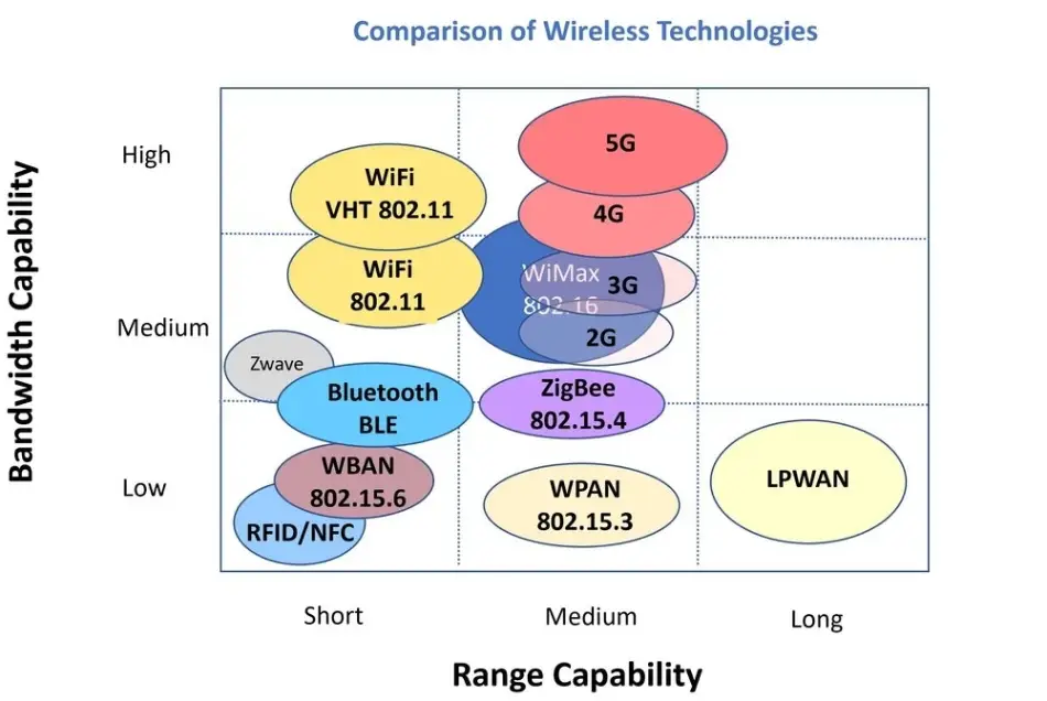
LoRa vs LoRaWAN
LoRaWAN (Long Range Wide Area Network) is a network protocol designed specifically to work with LoRa technology. While LoRa manages the data transmission at the physical level, LoRaWAN defines how devices communicate within a network. This includes specifying how data packets are sent between end devices (like sensors) and gateways, which then forward data to a central server. LoRaWAN organizes network activity, controls data transmission timing, and enforces security measures, such as encryption and device authentication, to ensure secure and efficient communication. Additionally, LoRaWAN has built-in features to optimize network performance, like Adaptive Data Rate (ADR), which adjusts data rates and power based on each device’s location and network conditions.
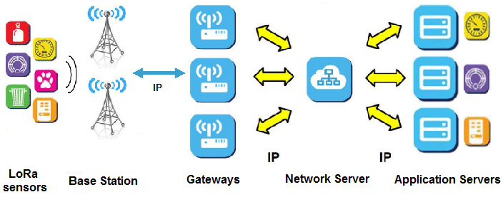
In a LoRa-based network, LoRa handles the hardware aspect of communication, enabling the transmission of data over long distances with minimal power. LoRaWAN, on the other hand, handles the network management side, ensuring that thousands of devices can communicate efficiently within the same network. While LoRa ensures that data can physically reach its destination, LoRaWAN organizes, secures, and manages that data to maintain a structured, scalable, and secure network.
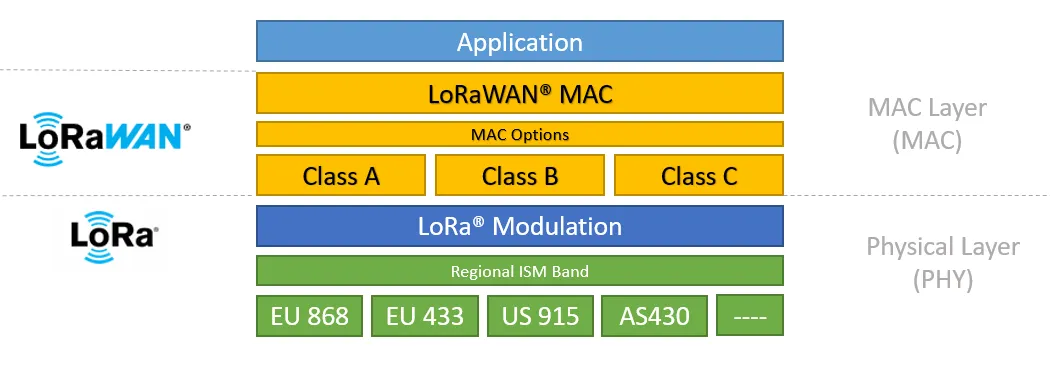
There are three classes of traffic in LoRaWAN network namely Class A, Class B and Class C. Class A is the most energy-efficient mode and is ideal for battery-powered devices that need to operate for long periods. Devices in Class A initiate all communication, which means they only send data when they have something to report (like a sensor reading). After transmitting data, the device opens two short receive windows to check if the network has a downlink message. If no message is received, the device goes back to sleep until it has new data to send, conserving battery power. Class B devices have scheduled receive windows in addition to the windows in Class A. They synchronize with the network using periodic beacons sent by the gateway, allowing the network to know when the device will be ready to receive data. This feature enables the network to send messages to Class B devices at specific times, reducing latency compared to Class A. Class C devices are always listening for downlink messages, except when they are transmitting data. This means that they can receive messages from the network with minimal delay, making Class C ideal for applications that need low-latency communication and constant responsiveness.
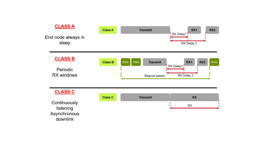
LoRa Technology
Chirp Spread Spectrum and Spread Factor
Chirp Spread Spectrum (CSS) is a modulation technique used by LoRa to enable long-range, low-power wireless communication with strong interference resistance. In CSS, data is transmitted using chirps—signals that increase or decrease in frequency over time. These chirps spread the data across a wide range of frequencies, making it resilient to interference and suitable for long-distance communication. Unlike narrowband signals, which are susceptible to noise and interference, CSS spreads the energy of the signal over a broader bandwidth, improving the reliability of the transmission even in challenging environments.
The Spread Factor (SF) is a key parameter in CSS and controls the duration and rate of each chirp, impacting both range and data rate. In LoRa, the spread factor can range from SF7 to SF12, where higher spread factors result in slower data rates but increase the transmission range. Mathematically, the data rate Rb in LoRa is given by the equation:

Spread Factor parameter affecting latency and error rate in LoRa communication. Huge SF value will produce a low error-rate communication with high latency while smaller SF value will produce a lower latency communication with huge error rate. The effect of Spread Factors and Chirp Spread Spectrum is visualized as below:
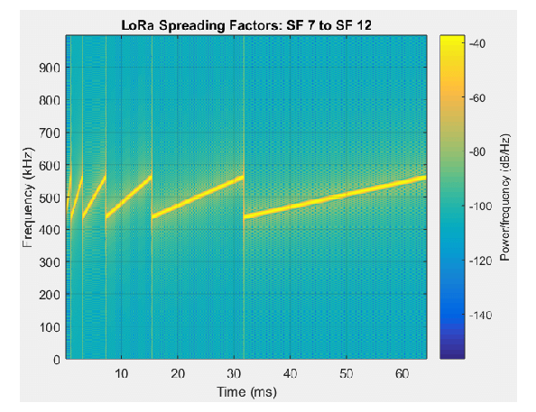
Each symbol to be transmitted will be modulated like below: