Telecommunication
Module 3 - Propagasi Signal LoRa
Part 1 - Theory
LoRa (& LoRaWAN)
1. Introduction
IoT devices can collect and exchange data, monitor and control various processes, and enable smart solutions for domains such as agriculture, health, smart cities, and industry. However, IoT devices also face several challenges, such as limited battery life, low data rates, long ranges, and security issues.
LoRa
LoRa and LoRaWAN are two technologies aimed at overcoming these challenges and providing a low-power, long-range, and secure wireless communication platform for IoT applications.
- LoRa is the physical layer technology that uses a proprietary modulation technique based on Chirp Spread Spectrum (CSS) to encode data onto radio waves.
- LoRaWAN is the network layer protocol that defines how LoRa devices communicate with each other and with a central server, utilizing a star-of-stars topology.
2. LoRa Modulation
LoRa (Long Range) is a wireless modulation technique enabling long-distance communication with low power consumption. It operates in license-free sub-gigahertz frequency bands (e.g., 433 MHz, 868 MHz, 915 MHz) and achieves data rates ranging from 0.3 kbit/s to 27 kbit/s, depending on modulation parameters.
Chirp Spread Spectrum (CSS)
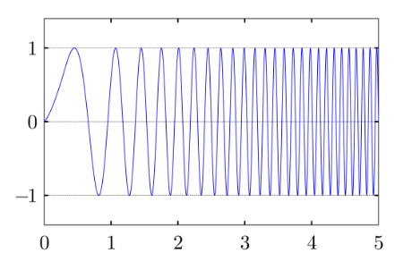
Linear frequency modulated up (upchirp) in the time domain
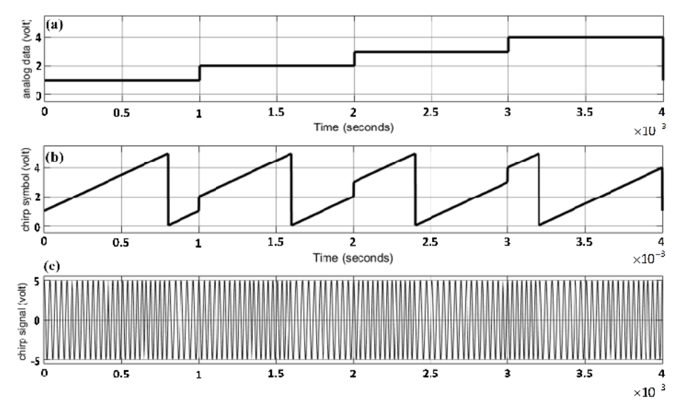
Four cyclic-shift chirp symbols and signals: (a) analog data, (b) 4-cyclic shift chirp symbols, and (c) 4-cyclic shift chirp signal.
CSS uses chirp pulses to transmit data. A chirp is a signal whose frequency increases (upchirp) or decreases (downchirp) linearly over time.
- Cyclic Shift Chirp: A chirp that wraps around when it reaches the maximum or minimum frequency. These are used to encode symbols (units of information).
- Advantages: CSS spreads the signal over a wide bandwidth, increasing immunity to noise and interference. It provides high processing gain and can handle the Doppler effect effectively.
LoRa Parameters
The performance of LoRa modulation is defined by three main configurable parameters:
- Bandwidth (BW): The frequency range of the signal (Use 923MHz for Asia)
- Spreading Factor (SF): The number of bits per symbol (ranges from SF7 to SF12).
- Higher SF = More range, higher sensitivity, but lower data rate and longer transmission time (airtime).
- Lower SF = Faster data rate, shorter range.
- Coding Rate (CR): Adds redundancy for error correction (4/5, 4/6, 4/7, 4/8). Higher redundancy improves reliability but decreases data rate.
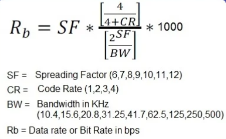
LoRa Data Rate Formula
The data rate can be calculated using the following formula:
3. Signal Characteristics & Propagation
Understanding radio characteristics is crucial for optimizing LoRa links.
RSSI and SNR
- RSSI (Received Signal Strength Indicator):
- Represents the received signal power in dBm (decibel-milliwatts).
- It is typically a negative value; values closer to 0 indicate a stronger signal (e.g., -30 dBm is stronger than -100 dBm).
- The practical noise floor for LoRa receivers is often around -120 dBm.
- SNR (Signal-to-Noise Ratio):
- The ratio of signal power to noise power, expressed in dB.
- Positive SNR: Signal power is greater than noise power.
- Negative SNR: Signal power is lower than noise power.
- Unlike standard FSK modulation, LoRa can demodulate signals with an SNR as low as -20 dB (at SF12), allowing communication even when the signal is buried below the noise floor.
Radio Propagation and Free Space Loss
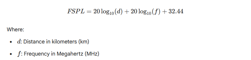
- Free Space Path Loss (FSPL):
- As a radio signal travels through space, its power density decreases. This attenuation is known as FSPL.
- Loss increases with distance and frequency.
- The Friis transmission equation for FSPL in dB is:

- Propagation Factors:
- Line of Sight (LoS): The direct path between transmitter and receiver yields the strongest signal.
- Fresnel Zone: An elliptical region around the LoS path. Obstructions within this zone (buildings, trees, ground) cause diffraction and signal loss. For optimal performance, at least 60% of the first Fresnel zone must be clear.
Part 2 - Hands On
4. Practicum: LoRa Implementation on ESP32
A. Hardware Setup (Wiring)
Connect the SX1276/RFM95 module to the ESP32 using the standard SPI configuration:
| LoRa Pin | ESP32 GPIO | Function |
|---|---|---|
| GND | GND | Ground |
| 3.3V | 3.3V | Power (Do not use 5V) |
| MISO | GPIO 19 | SPI Master In Slave Out |
| MOSI | GPIO 23 | SPI Master Out Slave In |
| SCK | GPIO 18 | SPI Clock |
| NSS/CS | GPIO 5 | Chip Select |
| RST | GPIO 14 | Reset |
| DIO0 | GPIO 26 | Interrupt (IRQ) |
B. Software Preparation
- Install the "LoRa by Sandeep Mistry" library via the Arduino Library Manager.
- Ensure the frequency (
433E6,868E6, or915E6) matches your hardware module.
C. Experiment 1: Basic Sender & Receiver
Sender Code:
#include <SPI.h>
#include <LoRa.h>

// Pin Definitions
#define SS_PIN    5
#define RST_PIN   14
#define DIO0_PIN  26
#define BAND      923E6

int counter = 0;

void setup() {
  Serial.begin(115200);
  while (!Serial);
  Serial.println("LoRa Sender");
  LoRa.setPins(SS_PIN, RST_PIN, DIO0_PIN);

  if (!LoRa.begin(BAND)) {
    Serial.println("Starting LoRa failed!");
    while (1);
  }
}

void loop() {
  Serial.print("Sending packet: ");
  Serial.println(counter);

  LoRa.beginPacket();
  LoRa.print("hello ");
  LoRa.print(counter);
  LoRa.endPacket();

  counter++;
  delay(5000);
}More Resources
Resources:
- ESP32 with LoRa using Arduino IDE – Getting Started
- LoRa Duplex communication with Sync Word Code
- Lora Repo Root LoRa API