
1. Introduction to VHDL
1.1 What is VHDL
VHDL is an acronym for VHSIC HDL or, more completely, Very High-Speed Integrated Circuit Hardware Description Language. VHDL is a language used to describe hardware, so its writing style cannot be equated with high/low-level programming languages. A VHDL model or program can be translated into an actual digital circuit quickly with the help of software and, of course, according to specific needs; this process is known as synthesis. The resulting circuit can also be tested using VHDL to ensure it works according to the user's requirements. Before proceeding to the main material, readers are reminded to understand the concepts of Basic Digital Circuits (DSD) for ease in describing and designing hardware.
1.2 VHDL Syntax
Because VHDL is a language used to describe hardware, in addition to the correct output, tidy program writing is also needed to make it easier to understand. The following are VHDL writing conventions that need to be observed:
-
Case Sensitivity : VHDL is not case-sensitive, meaning that both uppercase and lowercase letters are recognized as the same object.
-
White Space : VHDL is not sensitive to white space, meaning that creating space using either a tab or a space bar has the same meaning.
-
Comments : Like programming languages in general, VHDL also has comments, which are made by using the
--sign. -
Parentheses : In VHDL, there are open and close parentheses
()which are used for precedence, giving a higher priority to the statement within them. -
VHDL Statements : Statements in VHDL always end with a
;or semi-colon. -
If, case, and loop Statements
-
Every
ifstatement is followed by athencomponent. -
Every
ifstatement ends withend if;. -
Else ifin VHDL is written aselsif. -
Every
casestatement ends withend case;. -
Every
loopstatement is terminated withend loop;.
-
-
Identifiers/Variables : Identifiers or variables in VHDL can use a combination of letters (A-Z and a-z) and numbers (0-9), must not end with an
_, and can have an unlimited length. It is important to name variables according to their function so they are easy to understand.
1.3 VHDL Operator
Operators in VHDL are grouped into 7 types: logical, relational, shift, adding, sign, multiplying, and others. The order of this list also describes the precedence of the operators. The following is a complete description of these operators:
- Logical
| Operator Type | ||||||
| Logical | and | or | nand | nor | xor | xnor |
- Relational
| Operator | Name | Explanation |
A = B |
equivalence | is A equivalent to B? |
A /= B |
non-equivalence | is A not equivalent to B? |
A < B |
less than | is A less than B? |
A <= B |
less than or equal | is A less than or equal to B? |
A > B |
greater than | is A greater than B? |
A >= B |
greater than or equal | is A greater than or equal to B? |
- Shift
| Operator | Name | Example | Result | |
| logical | sll | shift left logical | result <= "10010101" sll 2 | "01010100" |
| srl | shift right logical | result <= "10010101" srl 3 | "00010010" | |
| arithmetic | sla | shift left arithmetic | result <= "10010101" sla 3 | "10101111" |
| sra | shift right arithmetic | result <= "10010101" sra 2 | "11100101" | |
| rotate | rol | rotate left | result <= "10100011" rol 2 | "10001110" |
| ror | rotate right | result <= "10100011" ror 2 | "11101000" |
- Arithmetic
| Operator | Name | Comment | |
| adding | + | addition | |
| - | subtraction | ||
| & | concatenation |
can operate only on specific types
|
|
| sign | + | identity | unary operator |
| - | negation | unary operator | |
| multiplying | * | multiplication | |
| / | division |
often limited to powers of two
|
|
| mod | modulus |
can operate only on specific types
|
|
| rem | remainder |
can operate only on specific types
|
|
| miscellaneous | ** | exponentiation |
often limited to powers of two
|
| abs | absolute value |
1.4 Data Objects
In VHDL, there are 4 types of Data Objects: signals, variables, constants, and files. The way to declare a data object for all types is more or less the same, as follows:
| VHDL data object | Declaration form |
| Signal | signal sig_name : sig_type:=initial_value; |
| Variable | variable var_name : var_type:=initial_value; |
| Constant | constant const_name : const_type:=initial_value; |
Assignment Operator
The assignment operator in VHDL has the same function as in programming languages in general, but its syntax is slightly different. There are two types of assignments that can be performed, namely for signals and variables:
-
Signal : The
<=operator is used to assign a value to a signal. -
Variable : The
:=operator is used to assign a value to a variable.
Standard Data Types
In VHDL (VHSIC Hardware Description Language), there are various data types used to define the properties and types of variables, signals, and other objects in a hardware design. Here are some common data types in VHDL:
-
Signed : This data type is used to represent integers with a sign (signed integer). It is suitable for representing negative and positive numbers in hardware design.
-
Unsigned : This data type is similar to "Signed," but it is only used to represent non-negative integers (unsigned integers).
-
STD_LOGIC : This data type is used to represent a single logic signal that can have the values '0', '1', 'Z' (high impedance), 'U' (uninitialized), 'X' (don't care), 'W' (weak), or 'L' (weak low).
-
STD_LOGIC_VECTOR : This is a data type used to represent a vector of STD_LOGIC signals. You can use this type to represent a bus or a collection of logic signals in a hardware design.
-
Integer : This data type is used to represent whole numbers, positive or negative. It is often used for counting and managing numerical values in a design.
-
Boolean : This data type has two values, "True" or "False." It is used for conditioning and logical expressions.
1.5 Design Units
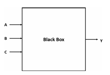
There are two important parts when designing a digital circuit using VHDL: "entity" and "architecture." These two units form a hierarchical design consisting of a black box and the components within it.
-
Entity : The entity is the first part of a VHDL design. It is the highest-level specification of a component or module in the design. In the entity, we define the component's external interface, including its inputs and outputs. The entity is the "black box" that describes what the component does and how it is accessed from the outside. The entity also defines the name of the component and the data types used.
-
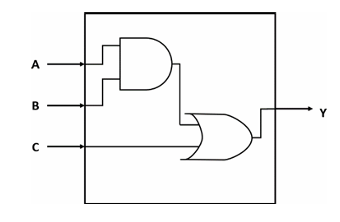
Architecture : The architecture is the second part of a VHDL design. This section describes how the component works internally, including how the signals defined in the entity are processed and connected within that component.
Concurrent Statement
In general, digital circuits are concurrent in nature (working in parallel or simultaneously). A change in the output of a concurrent circuit is directly influenced by a change in an input. Therefore, VHDL also adopts the concept of concurrency when processing the inputs and outputs of a circuit. A program in VHDL cannot be equated to software programming where instructions are executed sequentially. Instructions in VHDL are executed directly and simultaneously. However, with certain techniques, VHDL can also describe sequential circuits whose processes are executed in order.
A concurrent statement is a method used to describe the parallel operation of hardware in VHDL. There are four ways to describe a concurrent statement:
-
Concurrent signal assignment : This is the most common method used to describe a concurrent statement. The output of the circuit can change at any time when one of its inputs changes. Example description of a 3-input NAND and AND gate using concurrent signal assignment:
library IEEE;
use IEEE.STD_LOGIC_1164.ALL;

-- Entity defines the inputs and outputs (the "black box")
entity Logic_Gates is
    port (
        a, b, c : in  STD_LOGIC;          -- Three inputs
        y_and   : out STD_LOGIC;          -- Output for the AND gate
        y_nand  : out STD_LOGIC           -- Output for the NAND gate
    );
end Logic_Gates;

-- Architecture describes what happens inside the box
architecture Behavioral of Logic_Gates is
begin
    -- These two statements are CONCURRENT. They happen at the same time.
    y_and  <= a and b and c;
    y_nand <= a nand b and c;

end Behavioral;-
Conditional signal assignment : This method is used to describe a statement that has a single target signal but has more than one condition to evaluate. Example description of a 2-to-1 Mux using conditional signal assignment:
library IEEE;
use IEEE.STD_LOGIC_1164.ALL;

-- Entity for a 2-to-1 Multiplexer
entity Mux_2_to_1_Conditional is
    port (
        i0, i1 : in  STD_LOGIC;  -- The two data inputs
        sel    : in  STD_LOGIC;  -- The select line
        y      : out STD_LOGIC   -- The single output
    );
end Mux_2_to_1_Conditional;

-- Architecture using the "when/else" concurrent statement
architecture Behavioral of Mux_2_to_1_Conditional is
begin
    -- The output 'y' gets the value of 'i0' WHEN 'sel' is '0',
    -- ELSE it gets the value of 'i1'.
    y <= i0 when sel = '0' else i1;

end Behavioral;-
Selected signal assignment : This method differs from the conditional signal assignment method. In a selected signal assignment, the target is based on the evaluation of an expression. Example description of a 2-to-1 Mux with selected signal assignment:
library IEEE;
use IEEE.STD_LOGIC_1164.ALL;

-- Entity for a 2-to-1 Multiplexer
entity Mux_2_to_1_Selected is
    port (
        i0, i1 : in  STD_LOGIC;  -- The two data inputs
        sel    : in  STD_LOGIC;  -- The select line
        y      : out STD_LOGIC   -- The single output
    );
end Mux_2_to_1_Selected;

-- Architecture using the "with/select" concurrent statement
architecture Behavioral of Mux_2_to_1_Selected is
begin
    -- WITH the value of 'sel', SELECT the output 'y'
    with sel select
        y <= i0 when '0',       -- When sel is '0', y gets i0
             i1 when '1',       -- When sel is '1', y gets i1
             'X' when others;  -- For any other value (like 'U' or 'Z'), output 'X' (unknown)

end Behavioral;-
Process Statement : A method that can be used to execute many instructions sequentially. This section will be discussed in more detail in module 4 regarding Sequential Circuit Design.
library IEEE;
use IEEE.STD_LOGIC_1164.ALL;

-- Entity for a 2-to-1 Multiplexer
entity Mux_2_to_1_Process is
    port (
        i0, i1 : in  STD_LOGIC;  -- The two data inputs
        sel    : in  STD_LOGIC;  -- The select line
        y      : out STD_LOGIC   -- The single output
    );
end Mux_2_to_1_Process;

architecture Behavioral of Mux_2_to_1_Process is
begin

    -- This process block is sensitive to changes in i0, i1, or sel.
    -- If any of them change, the code inside runs sequentially.
    mux_process: process(i0, i1, sel)
    begin
        -- Inside a process, you use sequential statements like "if/then/else"
        if sel = '0' then
            y <= i0;
        else
            y <= i1;
        end if;
    end process mux_process;

end Behavioral;
Intermediate Signal
An intermediate signal has a function that is very similar to a signal declared in the entity. However, an intermediate signal is defined inside the architecture (before the begin keyword). Intermediate signals are very useful when the circuit we are describing becomes more complex. This signal can also act as a buffer to store data that has been processed in a specific part of the overall architecture.
architecture Behavioral of Counter is
    signal count_value : integer := 0; -- This is an example of an intermediate signal
begin
    process (clk)
    begin
        if rising_edge(clk) then
            count_value <= count_value + 1;
        end if;
    end process; -- ...
end Behavioral;
Multiple Bits Signal
With STD_LOGIC, we can represent the values '0' and '1' in the circuit we are describing (in the entity and architecture sections). In addition, we can also combine more than one bit into a single signal by using the STD_LOGIC_VECTOR signal type. This signal becomes a one-dimensional vector or array that represents data with a number of bits that can be set by the user.
entity Register is
    Port (
        data_in : in STD_LOGIC_VECTOR(7 downto 0);  -- 8-bit Input
        data_out : out STD_LOGIC_VECTOR(7 downto 0) -- 8-bit Output
    );
end entity Register;

architecture Behavioral of Register is
    signal internal_register : STD_LOGIC_VECTOR(7 downto 0); -- 8-bit signal
begin
    process (clk)
    begin
        if rising_edge(clk) then
            if (load = '1') then
                internal_register <= data_in; -- Loading data into the register
            else
                data_out <= internal_register; -- Outputting data from the register
            end if;
        end if;
    end process; -- ...
end Behavioral;
1.6 VHDL Architecture Models
In VHDL, there are several approaches to explaining or describing an architecture. Hardware can be described using these styles or models according to its needs and complexity. These approaches are divided into three types:
-
Data-flow style : The data-flow approach describes a circuit by showing the relationship between the inputs and outputs of the components in the VHDL language. Concurrent signal assignment, conditional signal assignment, and selected signal assignment are the statements used in the data-flow style.
-
Behavioral style : The behavioral style approach doesn't describe how the circuit is implemented when synthesized. Instead, the behavioral style models how the circuit's output reacts to its inputs. The main component of the behavioral style is the process statement.
-
Structural style : The structural style approach is essentially a method that supports the interconnection of black boxes or entities. This style enables modular design, allowing you to connect previously separate components into a single circuit or entity. The structural style is commonly used when a circuit becomes increasingly complex, as it simplifies the description process.