Theory
Objective
- Understand basic digital arithmetic using adders and subtractors.
Theory
In digital arithmetic, basic operations like addition, subtraction, multiplication, and division are all based on binary. These basic arithmetic operations are accomplished by using digital circuits called adders and subtractors.
1. Half Adder and Full Adder
In digital arithmetic, an adder is used to perform addition between 2 2-bit binary numbers. The half adder performs addition between bits A and B, producing outputs **S (sum) and C (carry). **
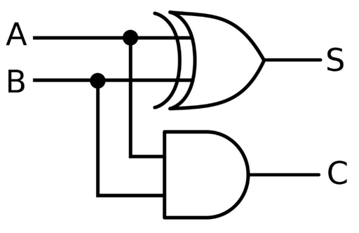
Figure 1-1: Half-Adder
Half-Adder Truth Table:
| A | B | S | C |
|---|---|---|---|
| 0 | 0 | 0 | 0 |
| 0 | 1 | 1 | 0 |
| 1 | 0 | 1 | 0 |
| 1 | 1 | 0 | 1 |
The simple adder adds the two bits together and represents them in sum (2^0) and carry (2^1).
Using this truth table, the half adder can be designed using Karnaugh maps, where the output S follows the logic of the XOR gate, and C follows the logic of the AND gate. In the half adder, we only consider inputs A and B.
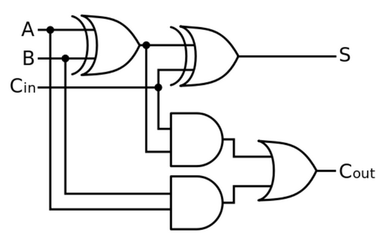
Figure 1-2: Full Adder
Truth Table for Full Adder:
| A | B | Cin | S | Cout |
|---|---|---|---|---|
| 0 | 0 | 0 | 0 | 0 |
| 0 | 0 | 1 | 1 | 0 |
| 0 | 1 | 0 | 1 | 0 |
| 0 | 1 | 1 | 0 | 1 |
| 1 | 0 | 0 | 1 | 0 |
| 1 | 0 | 1 | 0 | 1 |
| 1 | 1 | 0 | 0 | 1 |
| 1 | 1 | 1 | 1 | 1 |
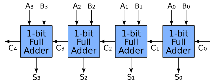
The full adder is a more advanced version of the half-adder, having added carry-in and carry-out parts to accomodate higher level additions. By using full adders, a Ripple Carry Adder can be created by connecting Cout from the less significant bit to Cin of the more significant bit.
Figure 1-3: Ripple Carry Adder. We can analogize this as a chain of adders, each working on a different power of two (such as 2^3 <- 2^2 <- 2^1 <- 2^0).
2. Half and Full Subtractor
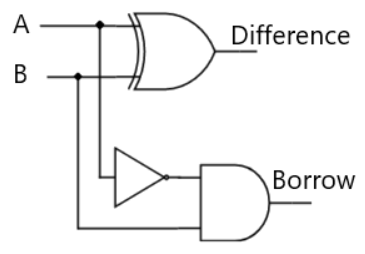
Opposite to adders, the subtractor is used to perform binary subtraction between 2 bits. A half subtractor performs subtraction between A and B, producing outputs D (difference) and Bo (borrow).
Figure 2-1: Half Subtractor
Truth Table for Half Subtractor:
| A | B | D | Bo |
|---|---|---|---|
| 0 | 0 | 0 | 0 |
| 0 | 1 | 1 | 1 |
| 1 | 0 | 1 | 0 |
| 1 | 1 | 0 | 0 |
Here, through boolean simplification / K-Map, D follows the same logic as the XOR gate, and Bo follows the logic A' . B.
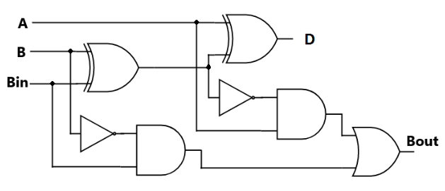
Figure 2-2: Full Subtractor
Truth Table for Full Subtractor:
| A | B | Bin | D | Bout |
|---|---|---|---|---|
| 0 | 0 | 0 | 0 | 0 |
| 0 | 0 | 1 | 1 | 1 |
| 0 | 1 | 0 | 1 | 1 |
| 0 | 1 | 1 | 0 | 1 |
| 1 | 0 | 0 | 1 | 0 |
| 1 | 0 | 1 | 0 | 0 |
| 1 | 1 | 0 | 0 | 0 |
| 1 | 1 | 1 | 1 | 1 |
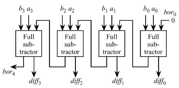
Like the full adder, the full subtractor has an additional input, Bin (borrow in), which comes from the Bout of another full subtractor. By using full subtractors, a Ripple Borrow Subtractor can be created by connecting Bout from the less significant bit to Bin of the more significant bit.
Figure 2-3: Ripple Borrow Subtractor

