Theory
1. Multiplexer
A multiplexer has multiple input pins, but only has one output pin. This circuit gives an output based on which input pin is chosen.

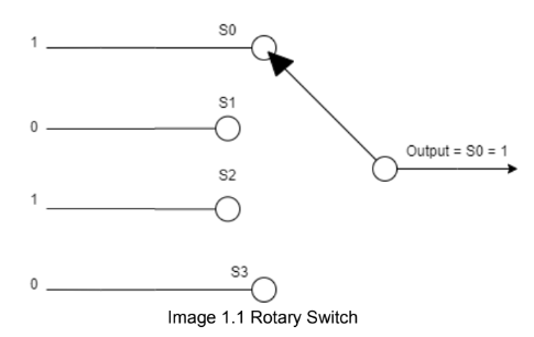
To explain further about how multiplexer works, we can imagine it as a rotary switch that works just like how multiplexers do. In the image above, there are 4 inputs from S0 to S3. Every input (from S0 to S3) has a signal between 1 or 0. The switch now is choosing to input S0, so the output of the rotary switch is the same as S0 (in this case is signal 1). Different from the rotary switch mentioned above, a multiplexer works by using a selector signal.
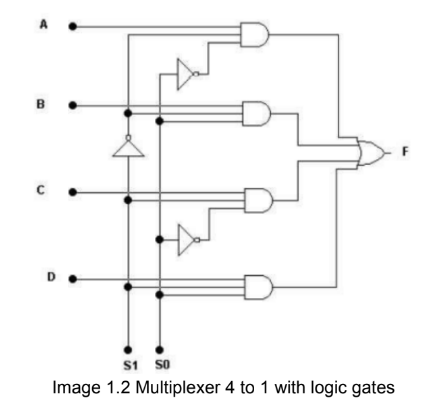
Multiplexers can also be built by primitive logic gates (AND, OR, NOT gates). To get the idea, see the image below (image 1.2).

How a Multiplexer Works
- Input: The multiplexer receives multiple inputs, in this case/image above, its A to D.
- Selector: The selector signals determine which input will be passed to the output. In a 4-to-1 multiplexer, two selector signals (e.g., S1 and S0) are needed to select one of the four inputs.
- Output: Based on the combination of selector signals, the multiplexer forwards the value from the selected input to the output.
For example:
- If S1 = 0 and S0 = 0, input A is selected since its the first input (0 index, where 1st = 0, and 2nd = 1,etc).
- If S1 = 0 and S0 = 1, input B is selected since its the second input (0 index, where 1st = 0, and 2nd = 1,etc).
- And so on, with different selector combinations choosing different inputs.
Truth Table of a 4-to-1 Multiplexer
| S1 | S0 | Output |
|---|---|---|
| 0 | 0 | A |
| 0 | 1 | B |
| 1 | 0 | C |
| 1 | 1 | D |
Multiplexers are useful in digital applications, especially when managing multiple data sources that need to be routed to a single destination. Remember that to build a custom multiplexer with logic gates, we need to derive the boolean function first with a truth table.
2. Demultiplexer
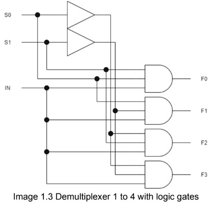
A demultiplexer is the opposite of a multiplexer; it has one input pin and multiple output pins. The signal or data from the input pin is directed to the selected output pin. A selector signal is also used in a demultiplexer to determine which output pin will receive the input signal. The image below shows a logic gate diagram of a demultiplexer:

In this diagram, the signal on the IN pin will be transmitted to the chosen output. The output will be selected by the signals S0 and S1. In the circuit above, if an output pin is not selected, it will receive a signal of 0.
How a Demultiplexer Works
- Input: The demultiplexer takes a single input signal from the IN pin.
- Selector: The selector signals (S0 and S1) determine which output pin the input signal will be directed to.
- Outputs: The selected output pin receives the input signal, while the other output pins receive a signal of 0.
Truth Table of a 1-to-4 Demultiplexer
| S1 | S0 | Output 0 | Output 1 | Output 2 | Output 3 |
|---|---|---|---|---|---|
| 0 | 0 | IN | 0 | 0 | 0 |
| 0 | 1 | 0 | IN | 0 | 0 |
| 1 | 0 | 0 | 0 | IN | 0 |
| 1 | 1 | 0 | 0 | 0 | IN |
Thus, the demultiplexer enables the distribution of a single input signal to one of several output lines based on the selector signals.
