3. Testbench Architecture Models
3.1 Testbench for Combinational Circuit
There are three architectural models for changing the value of inputs in a testbench. For example, if we want to make a testbench for a half adder entity below, we could use three methods:
library IEEE;
use IEEE.STD_LOGIC_1164.all;

entity half_adder is
    Port (
        a, b       : in STD_LOGIC;
        sum, carry : out STD_LOGIC
    );
end half_adder;

architecture arch of half_adder is
begin

    sum <= a xor b;
    carry <= a and b;

end arch;
3.1.1 Simple Testbench
This method is very similar to the dataflow style of VHDL programming. Values are directly assigned to input signals using the <= symbol. The difference is that each value assignment is separated by the after keyword, which indicates that the value will change after the testbench has run for the specified amount of time. For example, '1' after 60 ns means the value of the signal will change from '0' to '1' after the simulation has run for 60 ns from the very beginning.
library IEEE;
use IEEE.STD_LOGIC_1164.all;

entity half_adder_tb is
end half_adder_tb;

architecture tb of half_adder_tb is

    -- component declaration for half_adder
    component half_adder is
        Port (
            a, b       : in STD_LOGIC;
            sum, carry : out STD_LOGIC
        );
    end component;

    -- signal declaration for input/output stimulus
    signal a, b       : STD_LOGIC;    -- Input
    signal sum, carry : STD_LOGIC;    -- Output

begin
    -- component instantiation to connect tb to entity
    UUT: half_adder port map (
        a => a,
        b => b,
        sum => sum,
        carry => carry
    );

    -- input assignment (simple testbench)
    a <= '0', '1' after 20 ns, '0' after 40 ns, '1' after 60 ns;
    b <= '0', '1' after 40 ns;

end tb;
3.1.2 Testbench Using a process Statement
This method is similar to the behavioral style of VHDL programming, which uses a process statement. In this approach, every line of code inside the process is executed sequentially, one by one, much like in a typical programming language.
-- input assignment (process testbench)
tb1: process
    constant period    : time := 20 ns;
    begin
        a <= '0';
        b <= '0';
        wait for period;

        a <= '0';
        b <= '1';
        wait for period;

        a <= '1';
        b <= '0';
        wait for period;

        a <= '1';
        b <= '1';
        wait for period;

        wait; -- wait until the end of time
    end process;
3.1.3 Testbench Using a Look-up Table
This method is an extension of the process-based testbench. Instead of assigning each combination of values one by one, this method works by storing the combinations in a separate variable, called a look-up table (which can be a signal or a constant).
-- input assignment (look-up table testbench)
tb1: process
    constant period    : time := 20 ns;
    constant stream_a  : STD_LOGIC_VECTOR(0 to 3) := ('0', '1', '0', '1');
    constant stream_b  : STD_LOGIC_VECTOR(0 to 3) := ('0', '0', '1', '1');

    begin
        a <= stream_a(0);
        b <= stream_b(0);
        wait for period;

        a <= stream_a(1);
        b <= stream_b(1);
        wait for period;

        a <= stream_a(2);
        b <= stream_b(2);
        wait for period;

        a <= stream_a(3);
        b <= stream_b(3);
        wait for period;

        wait; -- wait until the end of time
    end process;
You can also use for loop for a more efficient implementation, but more of it will be covered in Module 6 and it's not recommended for this module.
3.2 Testbench for Sequential Circuit
A testbench for a sequential circuit is not much different from a testbench for a combinational circuit. The main difference is the need for several additional inputs, including a Clock and a Reset.
3.2.1 Clock Process
The clock is the heartbeat of a sequential circuit. In a testbench, the clock signal must be generated continuously throughout the simulation to drive the Unit Under Test (UUT). This is almost always done using a dedicated, independent process.
-- Inside of testbench architecture
    constant period    : time := 20 ns;    -- clock period
    signal clk         : STD_LOGIC;        -- clock signal

begin
    clk_generator : process
    begin
        clk <= '0';
        wait for period/2;
        clk <= '1';
        wait for period/2;
    end process;
3.2.2 Example of Testbench for Sequential Circuit
For example, we want to make a testbench for this updown counter entity:
library IEEE;
use IEEE.std_logic_1164.all;
use IEEE.numeric_std.all;

entity counter_updown is
    Port (
        RESET, CLK, LD, UP : in std_logic;
        DIN                : in std_logic_vector (3 downto 0);
        COUNT              : out std_logic_vector (3 downto 0)
    );
end counter_updown;

architecture my_count of counter_updown is
    signal t_cnt : unsigned(3 downto 0); -- internal counter signal
begin
    process (CLK, RESET)
    begin
        if (RESET = '1') then
            t_cnt <= (others => '0'); -- clear
        elsif (rising_edge(CLK)) then
            if (LD = '1') then t_cnt <= unsigned(DIN); -- load
            else
                if (UP = '1') then t_cnt <= t_cnt + 1; -- incr
                else t_cnt <= t_cnt - 1; -- decr
                end if;
            end if;
        end if;
    end process;
    COUNT <= std_logic_vector(t_cnt);
end my_count;
In this case, the testbench combines the three architectural models that were previously explained. The Clock signal uses a process statement, while the Reset signal uses the simple assignment method. The other inputs are assigned directly in the declaration section because their values will not change.
Additionally, it is important to note the presence of the max_clk variable, which is used to limit the number of clock cycles run by the testbench. If the clock cycles are not limited, the testbench will continue to run indefinitely unless the program is stopped manually.
library ieee;
use ieee.std_logic_1164.all;
use ieee.numeric_std.all;

entity counter_updown_tb is
end counter_updown_tb;

architecture arch of counter_updown_tb is
    component counter_updown is
        Port (
            RESET, CLK, LD, UP : in std_logic;
            DIN                : in std_logic_vector (3 downto 0);
            COUNT              : out std_logic_vector (3 downto 0)
        );
    end component;

    constant period    : time := 20 ns;    -- clock period
    constant max_clk   : integer := 11;    -- maximum clock cycle
    signal cnt         : integer := 0;     -- clock cycle counter

    constant LD        : std_logic := '0';              -- input
    constant UP        : std_logic := '1';              -- input
    signal DIN         : std_logic_vector(3 downto 0);  -- input
    signal RESET       : std_logic;                     -- input
    signal CLK         : std_logic;                     -- input
    signal COUNT       : std_logic_vector(3 downto 0);  -- output

begin
    UUT : counter_updown port map (RESET, CLK, LD, UP, DIN, COUNT);

    -- reset = '1' at the first clock cycle, then change to '0'
    reset <= '1', '0' after period/2;

    CLK_generator : process
    begin
        CLK <= '0';
        wait for period/2;
        CLK <= '1';
        wait for period/2;

        if(i < max_clk) then i <= i + 1;
        else wait;
        end if;
    end process;
end arch;
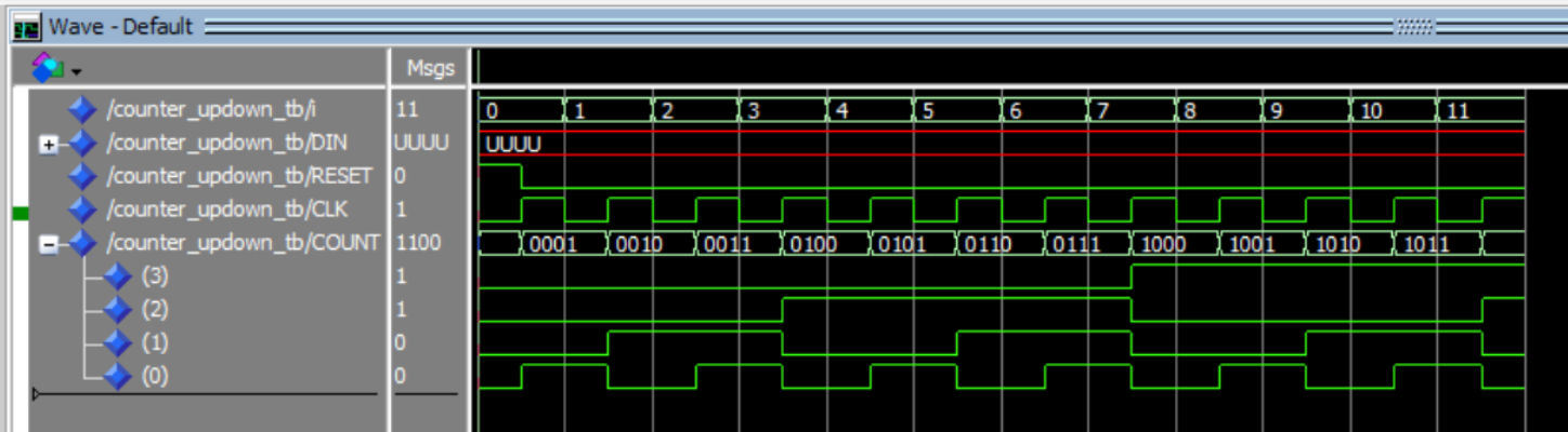
Here is the simulation result of the testbench above: