Microprogramming in VHDL
Microprogramming in VHDL
Microprogramming is a technique in computer design that involves using microinstruction sets or small steps executed by a microprocessor's control unit. VHDL often implements this using state or finite state machines (FSMs).
Instruction Set
An instruction set is a collection of instructions that a computer's microprocessor or CPU (Central Processing Unit) understands. Each CPU has its own instruction set consisting of a series of basic operations that the CPU can perform. These instructions include basic operations such as addition, subtraction, multiplication, data transfer, and logical operations. With VHDL, we can simulate the running of a processor when executing its instructions.
The instruction set of a computer architecture is one of the critical elements in the design of a CPU. It determines the types of operations the CPU can perform, the format of the instructions, and how the instructions are executed. Instruction sets can be divided into several categories, namely:
Arithmetic and Logic
- Addition, subtraction, multiplication, division
- Logical operations (AND, OR, NOT, XOR)
Data Transfer
- Data transfer between registers and memory
- Data transfer between internal registers
Flow Control Program
- Branching instructions (conditional and unconditional)
- Looping instructions
Input/Output
- Special instructions related to specific architectures or application needs
Code below is an example of an instruction set for a simple CPU to perform arithmetic and logic operations.
library IEEE;
use IEEE.STD_LOGIC_1164.ALL;
use IEEE.STD_LOGIC_ARITH.ALL;
use IEEE.STD_LOGIC_UNSIGNED.ALL;

entity Microprogram_ADD is
	Port ( clk : in STD_LOGIC;
		   reset : in STD_LOGIC;
		   start : in STD_LOGIC;
		   operand1 : out STD_LOGIC_VECTOR(7 downto 0);
		   operand2 : in STD_LOGIC_VECTOR(7 downto 0);
		   operand3 : in STD_LOGIC_VECTOR(7 downto 0)
		 );
end Microprogram_ADD;

architecture Behavioral of Microprogram_ADD is
	type State_Type is (FETCH, DECODE, EXECUTE, COMPLETE);
	signal state : State_Type := FETCH;
	signal counter : integer := 0;
	signal data_reg : STD_LOGIC_VECTOR(7 downto 0);
	signal add_result : STD_LOGIC_VECTOR(7 downto 0);
begin
	process(clk, reset)
	begin
		if reset = '1' then
			state <= FETCH;
			counter <= 0;
			data_reg <= (others => '0');
			add_result <= (others => '0');
		elsif rising_edge(clk) then
			case state is
				when FETCH =>
					if start = '1' then
						state <= DECODE;
					end if;
				when DECODE => --Microinstruction for decoding phase
					data_reg <= "00000001"; --Assume control signal for ADD
					counter <= counter + 1;
					if counter = 2 then
						state <= EXECUTE;
					end if;
				when EXECUTE => --Microinstruction for execution phase
					data_reg <= "00000010"; --Assume control signal for addition operation
					add_result <= operand2 + operand3;
					counter <= counter + 1;
					if counter = 3 then
						state <= COMPLETE;
					end if;
				when COMPLETE => --Microinstruction for completion phase
					data_reg <= "00000000"; --Reset control signals
					state <= FETCH; --Reset to initial state
			end case;
		end if;
	end process;
	operand1 <= add_result;
end Behavioral;
Based on the code above, the instruction set consists of four states: FETCH, DECODE, EXECUTE, and COMPLETE. The instruction set is designed to perform an addition operation. The operand2 and operand3 are input operands, while operand1 is the output operand. The start signal is used to initiate the operation. The data_reg signal is used to store the control signals for the microinstructions. The add_result signal stores the result of the addition operation.

State_Type is a user-defined type that defines the states of the CPU. The state signal is used to keep track of the current state of the CPU. The counter signal is used to count the number of clock cycles. The data_reg signal stores the control signals for the microinstructions. The add_result signal stores the result of the addition operation.
In this module, we will learn how to design a control unit using microprogramming in VHDL. We will also learn how to implement the control unit using a finite state machine (FSM) and microinstructions. To find out more about how to make a 16 bit CPU, see here
Central Processing Unit (CPU)
CPU has four main components:
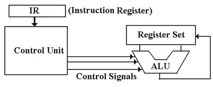
- The Control Unit (together with IR) interprets machine language instructions and issues control signals to make the CPU execute those instructions.
- ALU (Arithmetic Logic Unit), which performs arithmetic and logic operations.
- Set Register (File Register), which stores temporary results related to calculations. Special Registers are also used. The Control Unit also uses Special Registers.
- Internal bus structure for communication.

The function of the control unit is to decode the binary machine words in the IR (Instruction Register) and issue appropriate control signals, primarily to the CPU. These control signals are what cause the computer to execute its programs.
Control Unit Design
There are two related issues when considering control unit design:
- The complexity of the Instruction Set architecture and
- The microarchitecture used to implement the control unit. A computer's ISA (Instruction Set Architecture) is the set of assembly language instructions that the computer can execute. It can be viewed as an interface between the software (expressed as assembly language) and the hardware. More complex ISAs require more complicated control units. At some point in the development of computers, the complexity of the control unit becomes a problem for designers.
How Control Unit Works
The binary form of the instruction now resides in the IR (Instruction Register). The control unit decodes the instruction and generates the control signals required for the CPU to act according to the machine language instructions. The two main design categories here are hardwired and microprogrammed:
Hardwired → Control signals are generated as outputs from a series of basic logic gates; the inputs are from binary bits in the Instruction Register. Microprogram → Control signals are generated by a microprogram stored in the Control Read Only Memory.
Control Unit Microprogram
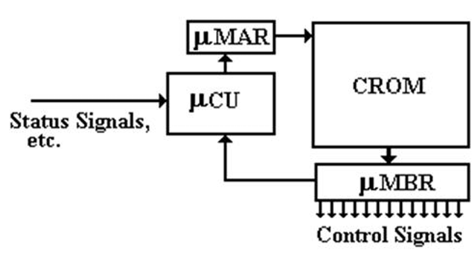
In the microprogrammed control unit, control signals correspond to bits in the micro-memory (CROM for Control Read Only Memory), which are read into the micro-MBR. This register is simply a set of D flip-flops, the contents of which are transmitted as signals.

The micro-control unit (CU) performs the following steps:
- Place the address into the micro-memory Address Register (µMAR),
- The control word is read from the Control Read-Only Memory,
- Place the microcode word into the micro-memory Buffer Register,
- The control signal is output.
