Theory
A. Binary Operation
In electrical components, data is represented as a stream of bits. These bits are processed in the components, creating processed bits of data. This process is called a binary operation. Binary operations are further classified into:
1. Parallel Operation
The parallel operation works instantly without a timer. Input bits are processed together at the same time, producing output bits in a short amount of time. This operation is very effective for quick outputs but is expensive for larger bits.
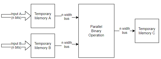
Figure 1-1: Parallel Operation Block Diagram In this design type, optimized design is key to produce efficient and cost effective designs.
2. Serial Operation
In serial operation, input bits are processed one by one, creating output sequentially. A timer ensures that the input produces the correct output and shifts the data in the correct order. Memory is also needed to store the input and output bits, often achieved using a shift register.
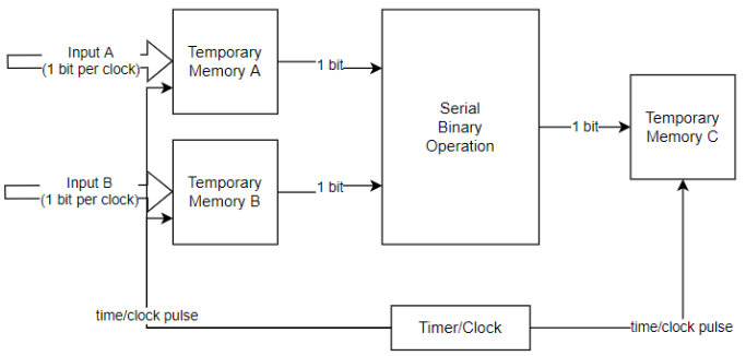 Figure 1-2: Serial Operation Block Diagram
The block doesn’t need a timer pulse since it works instantly for every input change. The output is also saved at every pulse, sequentially.
3. Combination
A combination of parallel and serial operations can be used to balance speed and cost. This hybrid operation requires a timer to mark the beginning and end of the serial part before and after the parallel part.
B. Register
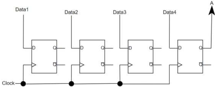
To save data in a digital circuit, a register is used. A register saves data using signal bits with flip-flops and states. Registers can be designed using a combination of serial and parallel operations, such as Serial Input Parallel Output (SIPO) and Parallel Input Serial Output (PISO) registers.
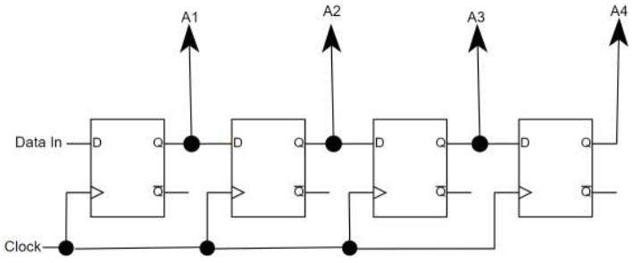
Figure 2-1: SIPO Register
Figure 2-2: PISO Register
The main component of a register is the flip flop, a clock (or enabler), input, and output. The main difference between parallel and serial is how the signal is handled. If more than one signal is handled simultaneously, then it is called parallel. If only one signal is handled one by one, then it is called serial.
C. Counter
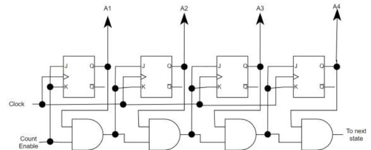
A counter is used to control sequences and execution steps in a logical circuit by counting bits. Counters consist of flip-flops that switch states in sequence. There are two types of counters:
- Synchronous Counter: All flip-flops are connected and controlled at the same time by the same external clock.
Figure 3-1: 4-bit Synchronous Counter
- Asynchronous Counter: Flip-flops are controlled by the output of the previous flip-flop, except for the first one, which is controlled by an external clock.
Figure 3-2: 4-bit Asynchronous Counter
Counters can count up, count down, or both, and may use different coding schemes, such as n-bit binary counters or n-bit BCD counters. A counter that counts from 0 to 9 (0000 to 1001) is called a decade counter.
Figure 4-1: 4-bit Decade Counter

