
1. Introduction to VHDL
1.1 What is VHDL
VHDL is an acronym for VHSIC HDL or, more completely, Very High-Speed Integrated Circuit Hardware Description Language. VHDL is a language used to describe hardware, so its writing style cannot be equated with high/low-level programming languages. A VHDL model or program can be translated into an actual digital circuit quickly with the help of software and, of course, according to specific needs; this process is known as synthesis. The resulting circuit can also be tested using VHDL to ensure it works according to the user's requirements. Before proceeding to the main material, readers are reminded to understand the concepts of Basic Digital Circuits (DSD) for ease in describing and designing hardware.
1.2 VHDL Syntax
Because VHDL is a language used to describe hardware, in addition to the correct output, tidy program writing is also needed to make it easier to understand. The following are VHDL writing conventions that need to be observed:
-
Case Sensitivity : VHDL is not case-sensitive, meaning that both uppercase and lowercase letters are recognized as the same object.
-
White Space : VHDL is not sensitive to white space, meaning that creating space using either a tab or a space bar has the same meaning.
-
Comments : Like programming languages in general, VHDL also has comments, which are made by using the
--sign. -
Parentheses : In VHDL, there are open and close parentheses
()which are used for precedence, giving a higher priority to the statement within them. -
VHDL Statements : Statements in VHDL always end with a
;or semi-colon. -
If, case, and loop Statements
-
Every
ifstatement is followed by athencomponent. -
Every
ifstatement ends withend if;. -
Else ifin VHDL is written aselsif. -
Every
casestatement ends withend case;. -
Every
loopstatement is terminated withend loop;.
-
-
Identifiers/Variables : Identifiers or variables in VHDL can use a combination of letters (A-Z and a-z) and numbers (0-9), must not end with an
_, and can have an unlimited length. It is important to name variables according to their function so they are easy to understand.
1.3 VHDL Operator
Operators in VHDL are grouped into 7 types: logical, relational, shift, adding, sign, multiplying, and others. The order of this list also describes the precedence of the operators. The following is a complete description of these operators:
- Logical
| Operator Type | ||||||
| Logical | and | or | nand | nor | xor | xnor |
- Relational
| Operator | Name | Explanation |
A = B |
equivalence | is A equivalent to B? |
A /= B |
non-equivalence | is A not equivalent to B? |
A < B |
less than | is A less than B? |
A <= B |
less than or equal | is A less than or equal to B? |
A > B |
greater than | is A greater than B? |
A >= B |
greater than or equal | is A greater than or equal to B? |
- Shift
| Operator | Name | Example | Result | |
| logical | sll | shift left logical | result <= "10010101" sll 2 | "01010100" |
| srl | shift right logical | result <= "10010101" srl 3 | "00010010" | |
| arithmetic | sla | shift left arithmetic | result <= "10010101" sla 3 | "10101111" |
| sra | shift right arithmetic | result <= "10010101" sra 2 | "11100101" | |
| rotate | rol | rotate left | result <= "10100011" rol 2 | "10001110" |
| ror | rotate right | result <= "10100011" ror 2 | "11101000" |
- Arithmetic
| Operator | Name | Comment | |
| adding | + | addition | |
| - | subtraction | ||
| & | concatenation |
can operate only on specific types
|
|
| sign | + | identity | unary operator |
| - | negation | unary operator | |
| multiplying | * | multiplication | |
| / | division |
often limited to powers of two
|
|
| mod | modulus |
can operate only on specific types
|
|
| rem | remainder |
can operate only on specific types
|
|
| miscellaneous | ** | exponentiation |
often limited to powers of two
|
| abs | absolute value |
1.4 Design Units
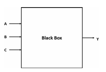
There are two important parts when designing a digital circuit using VHDL: "entity" and "architecture." These two units form a hierarchical design consisting of a black box and the components within it.
-
Entity : The entity is the first part of a VHDL design. It is the highest-level specification of a component or module in the design. In the entity, we define the component's external interface, including its inputs and outputs. The entity is the "black box" that describes what the component does and how it is accessed from the outside. The entity also defines the name of the component and the data types used.
library IEEE;
use IEEE.STD_LOGIC_1164.ALL;

-- The ENTITY describes the "black box" interface.
-- It defines the input and output ports.
entity Logic_Circuit is
    port (
        A, B, C : in  STD_LOGIC;  -- The three input pins
        Y       : out STD_LOGIC   -- The single output pin
    );
end Logic_Circuit;
-
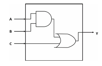
Architecture : The architecture is the second part of a VHDL design. This section describes how the component works internally, including how the signals defined in the entity are processed and connected within that component.
-- The ARCHITECTURE describes the internal logic.
-- It explains HOW the inputs are used to create the output.
architecture Dataflow of Logic_Circuit is
begin
    -- This single line of code represents the AND gate followed by the OR gate.
    Y <= (A and B) or C;
end Dataflow;
1.5 Data Objects
In VHDL, there are 4 types of Data Objects: signals, variables, constants, and files. The way to declare a data object for all types is more or less the same, as follows:
| VHDL data object | Declaration form |
| Signal | signal sig_name : sig_type:=initial_value; |
| Variable | variable var_name : var_type:=initial_value; |
| Constant | constant const_name : const_type:=initial_value; |
1.5.1 VHDL Signals
A signal in VHDL is the primary way to model a physical wire or connection in a hardware design. Declared within an architecture, its main purpose is to communicate data between different concurrent components, such as processes or logic gates. A signal is assigned a value using the <= operator, and this assignment is not immediate. it is scheduled to occur at a specific future time, which accurately reflects the signal propagation delay found in real-world circuits. This delayed behavior is essential for correctly modeling how different parts of a hardware design interact with each other. Signals is also only Declared in the declarative part of an architecture or package. There are two ways to declare signals :
Port Signal
A port signal is declared in the entity section of a VHDL design and represents an external connection. Its purpose is to define how the module sends and receives data from the outside world. Think of ports as the plugs and sockets on an appliance—they are the only way to interact with what's inside. You must specify a direction (or mode) for each port, such as in, out, inout, or buffer.
-- Port signals are declared inside the ENTITY
entity D_Flip_Flop is
    port (
        d, clk, rst : in  STD_LOGIC;  -- Input ports
        q           : out STD_LOGIC   -- Output port
    );
end D_Flip_Flop;

architecture Behavioral of D_Flip_Flop is
-- ... logic using the ports ...
end Behavioral;
Intermediate Signal
An intermediate signal is declared in the declarative part of the architecture and acts as an internal wire within your design. It is not visible from outside the module. Intermediate signals are essential for connecting different internal processes or concurrent statements, breaking down complex logic into simpler steps, or holding a value that needs to be used in multiple places within the architecture.
entity Complex_Gate is
    port (
        a, b, c, d : in  STD_LOGIC;
        y          : out STD_LOGIC
    );
end Complex_Gate;

-- Intermediate signal is declared inside the ARCHITECTURE
architecture Dataflow of Complex_Gate is
    -- This signal is an internal "wire" to hold a temporary result
    signal and_result_1 : STD_LOGIC;
begin
    -- The intermediate signal connects the output of the first AND gate
    -- to the input of the OR gate.
    and_result_1 <= a and b;
    y <= and_result_1 or (c and d);
end Dataflow;
1.5.2 VHDL Variables
A variable acts as temporary, local storage for calculations and does not represent a physical wire. It can only be declared and used inside a sequential block, such as a process (this will be explained more in module 3 : Behavioral Style) . The key distinction of a variable is its immediate update behavior. when a value is assigned using the := operator, the variable changes instantly and can be used in the very next line of code with its new value. This makes variables ideal for complex, multi-step algorithms where you need to store intermediate results without the delay and hardware overhead associated with a signal. Variables is also only Declared only inside a process, function, or procedure. It cannot be used to connect different processes.
library IEEE;
use IEEE.STD_LOGIC_1164.ALL;

-- Entity defines the inputs and outputs
entity Bit_Counter is
    port (
        data_in  : in  STD_LOGIC_VECTOR(7 downto 0); -- 8-bit input bus
        count_out: out INTEGER range 0 to 8          -- The final count
    );
end Bit_Counter;

-- Architecture shows the internal logic
architecture Behavioral of Bit_Counter is
begin
    -- A process is needed to use a variable
    count_process: process(data_in)
        -- 1. The variable is declared here, inside the process.
        -- It is initialized to 0 every time the process runs.
        variable bit_count : INTEGER := 0;
    begin
        -- Loop through each bit of the input signal
        for i in data_in'range loop
            if data_in(i) = '1' then
                -- 2. The variable is updated IMMEDIATELY.
                bit_count := bit_count + 1;
            end if;
        end loop;

        -- 3. The final result is assigned to the output signal.
        count_out <= bit_count;

    end process count_process;
end Behavioral;
1.5.3 VHDL Constant
A constant in VHDL is a data object that holds a fixed value which cannot be changed after it is declared using the constant NAME : TYPE := VALUE; syntax. Its primary purpose is to improve code readability and maintainability by assigning a descriptive name to a value, like using DATA_WIDTH instead of the number 8. This practice makes a design much easier to update, as changing the constant's value in its single declaration will automatically apply that change everywhere it's used, effectively acting like a labeled, unchangeable setting for your entire project. Constant can be declared in various places like a package, entity, architecture, or process.
-- First, define the constants in a package
package My_Design_Package is
    constant DATA_WIDTH : integer := 8;
    constant CLK_FREQ_HZ: integer := 50_000_000; -- 50 MHz
end package My_Design_Package;

-- Then, use the package in your design
library IEEE;
use IEEE.STD_LOGIC_1164.ALL;
use work.My_Design_Package.all; -- Makes our constants visible

entity My_Register_File is
    port (
        clk      : in  std_logic;
        data_in  : in  std_logic_vector(DATA_WIDTH - 1 downto 0); -- Uses the constant
        data_out : out std_logic_vector(DATA_WIDTH - 1 downto 0)  -- Uses the constant
    );
end My_Register_File;
1.5.5 Standard Data Types
In VHDL (VHSIC Hardware Description Language), there are various data types used to define the properties and types of variables, signals, and other objects in a hardware design. Here are some common data types in VHDL:
-
Signed : This data type is used to represent integers with a sign (signed integer). It is suitable for representing negative and positive numbers in hardware design.
-- Declaration
signal setpoint_signed    : SIGNED(7 downto 0);
signal feedback_signed    : SIGNED(7 downto 0);
signal error_value_signed : SIGNED(7 downto 0);

--  Usage Example: Calculate the difference between two signed values
error_value_signed <= setpoint_signed - feedback_signed;-
Unsigned : This data type is similar to "Signed," but it is only used to represent non-negative integers (unsigned integers).
-- Declaration
signal program_counter : UNSIGNED(15 downto 0);

-- Usage Example: Increment the counter in a clocked process
if rising_edge(clk) then
    program_counter <= program_counter + 1;
end if;-
STD_LOGIC : This data type is used to represent a single logic signal that can have the values '0', '1', 'Z' (high impedance), 'U' (uninitialized), 'X' (don't care), 'W' (weak), or 'L' (weak low).
-- Declaration
signal clk   : STD_LOGIC;
signal rst   : STD_LOGIC;
signal q_out : STD_LOGIC;

-- Usage Example: Using a reset signal to clear a register
if rst = '1' then
    q_out <= '0';
elsif rising_edge(clk) then
    -- ... other logic ...
end if;-
STD_LOGIC_VECTOR : This is a data type used to represent a vector of STD_LOGIC signals. You can use this type to represent a bus or a collection of logic signals in a hardware design (multiple bits).
-- Declaration
signal control_register : STD_LOGIC_VECTOR(7 downto 0);

-- Usage Example: Assigning a hexadecimal value to a control register
control_register <= x"A5"; -- Assigns the bit pattern "10100101"-
Integer : This data type is used to represent whole numbers, positive or negative. It is often used for counting and managing numerical values in a design.
-- Usage within a process
process(clk)
    -- Declaration (variable declared inside a process)
    variable i : INTEGER;
begin
    -- Usage Example: Controlling a loop a specific number of times
    for i in 0 to 15 loop
        -- ... perform an operation ...
    end loop;
end process;-
Boolean : This data type has two values, "True" or "False." It is used for conditioning and logical expressions.
-- Declaration
signal fifo_is_not_empty : BOOLEAN;
signal read_enable       : STD_LOGIC;

-- Usage Example: Using a boolean flag to control an operation
if fifo_is_not_empty = True then
    read_enable <= '1';
else
    read_enable <= '0';
end if;
1.6 VHDL Architecture Models
In VHDL, there are several approaches to explaining or describing an architecture. Hardware can be described using these styles or models according to its needs and complexity. These approaches are divided into three types:
-
Data-flow style : The data-flow approach describes a circuit by showing the relationship between the inputs and outputs of the components in the VHDL language. Concurrent signal assignment, conditional signal assignment, and selected signal assignment are the statements used in the data-flow style.
-
Behavioral style : The behavioral style approach doesn't describe how the circuit is implemented when synthesized. Instead, the behavioral style models how the circuit's output reacts to its inputs. The main component of the behavioral style is the process statement.
-
Structural style : The structural style approach is essentially a method that supports the interconnection of black boxes or entities. This style enables modular design, allowing you to connect previously separate components into a single circuit or entity. The structural style is commonly used when a circuit becomes increasingly complex, as it simplifies the description process.
No comments to display
No comments to display