
Vivado Simulation and Synthesis Tutorial
1.3 Vivado Tutorial
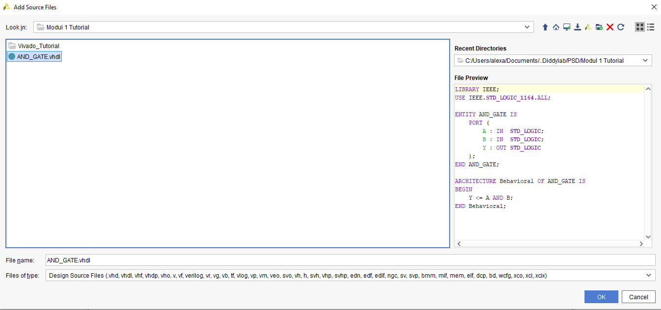
For this tutorial, we will use this code for reference :
LIBRARY IEEE;
USE IEEE.STD_LOGIC_1164.ALL;

ENTITY AND_GATE IS
    PORT (
        A : IN  STD_LOGIC;
        B : IN  STD_LOGIC;
        Y : OUT STD_LOGIC
    );
END AND_GATE;

ARCHITECTURE Behavioral OF AND_GATE IS
BEGIN
    Y <= A AND B;
END Behavioral;
1.3.1 Creating a new Vivado file
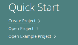
Create a new project
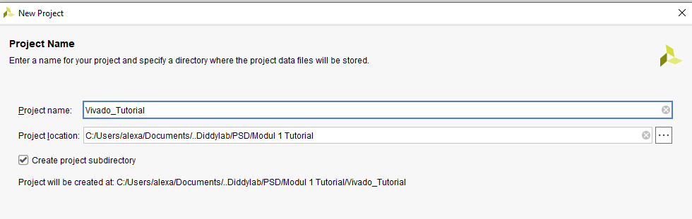
Enter your project name and where you want it to be saved
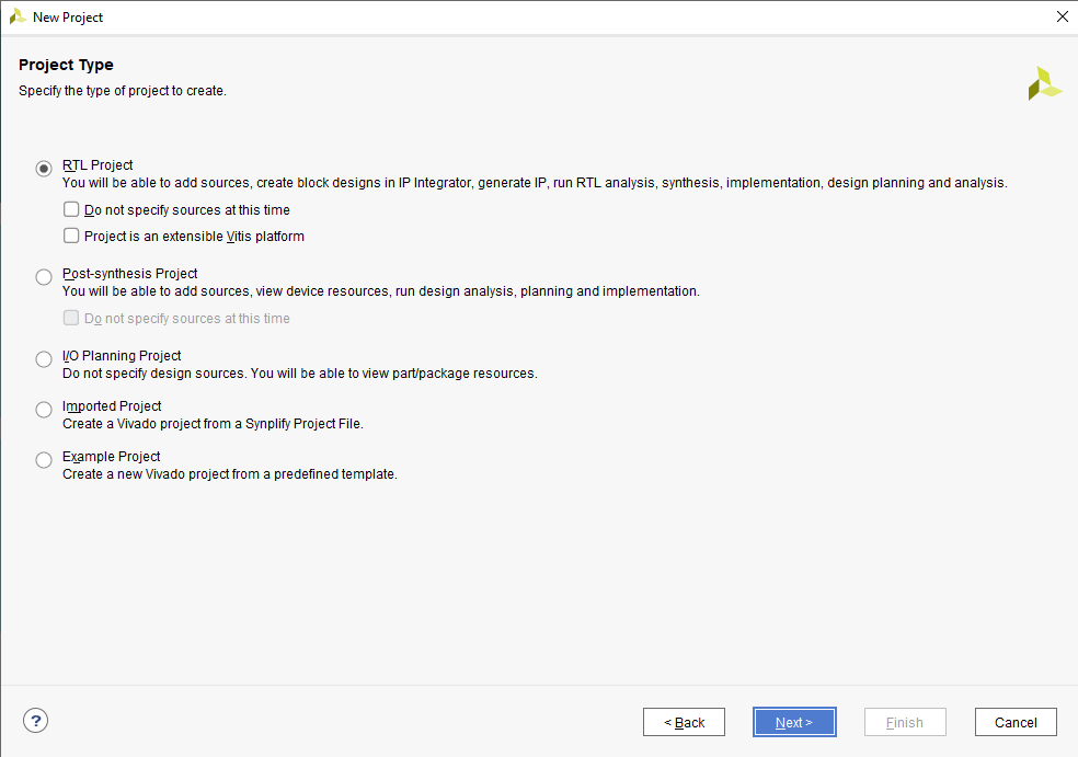
Choose RTL Project
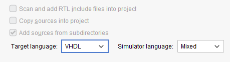
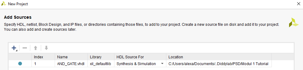
Change the target language into VHDL and add your VHDL code into the project
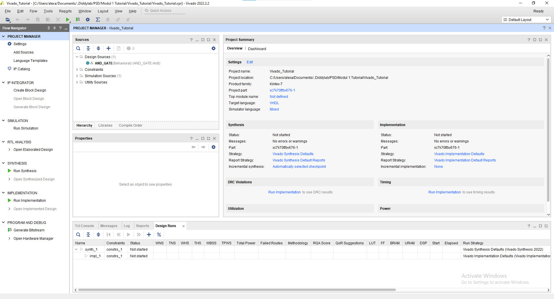
You may skip the add constraints page and also the default part proceed into the project creation. Finally you've created a new project and this will be your screen now.
1.3.2 Simulation Tutorial
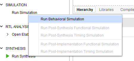
Click "Run Simulation" on the left part of the screen. And choose "Run Behavorial Simulation"
If there's any error warning, you may read and fix the error before proceeding into the simulation.
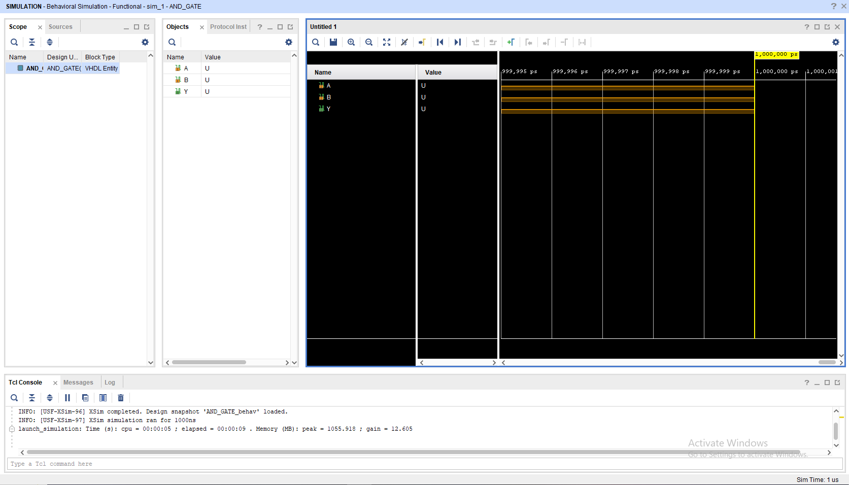
This will be your screen after you run the simulation.
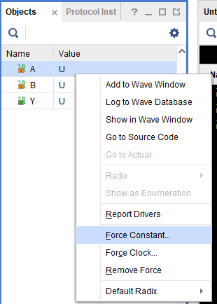
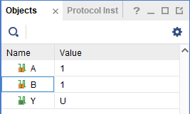
To add a signal, you may change the value in the objects part, choose "Force Constant" and change according to what you want to do. Remember to change the INPUT not the OUTPUT
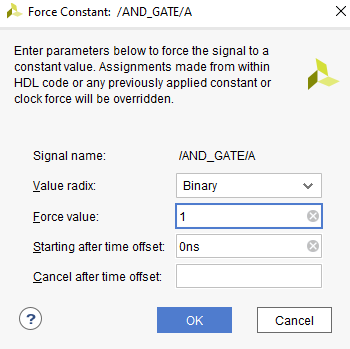
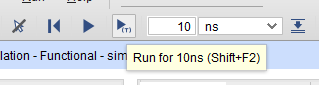
After changing the Value you may click the "Run for 10ns" on the top bar
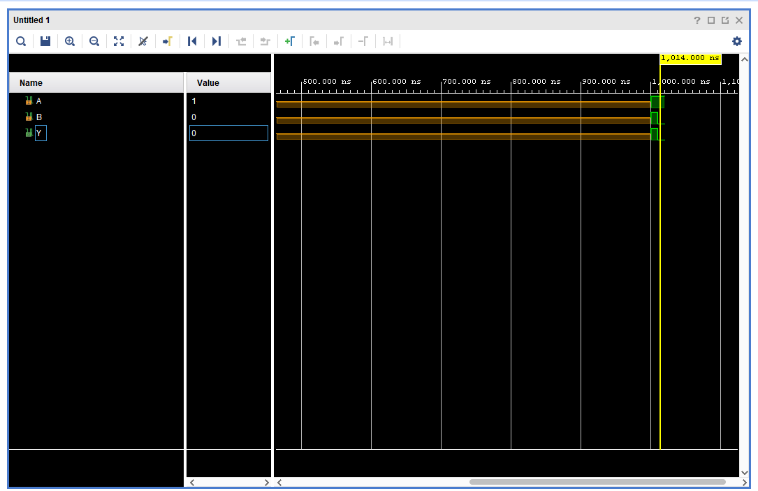
You may see that there's a new signal after you press the button
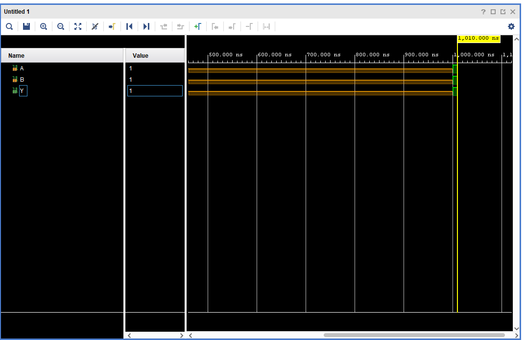
You may also move the yellow line with your cursor to switch to a different period of time on the waveform
NOTE : All of this is just a manual simulation tutorial. There are a way to do this automatically (Hint: Module 4).
To close simulation, you may click the top right button
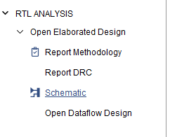
1.3.3 Synthesis Tutorial
Go to the "RTL Analysis" and run "Schematic" and if there's a notification just select "ok"
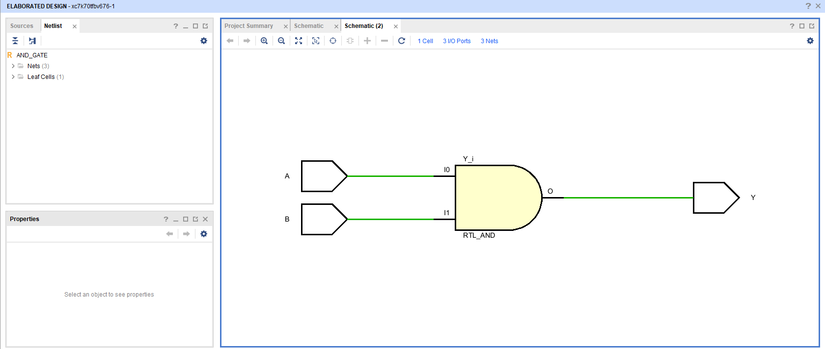
Wait until the elaborated design is finished and then you may see your VHDL code schematic.
No comments to display
No comments to display