
2. Addressing Modes
Due to how the AVR Architecture and its memory are organized, AVR instructions, including arithmetic instructions, must follow certain addressing methods. Addressing methods are how the control unit may access different data locations according to the instruction which are usually 16 - 32 bits in length. Those data locations may include general purpose registers, I/O registers, extended I/O registers, and the SRAM.
Single Register Direct (Rd)

Operates on a single general purpose register Rd with d being values 0 - 31 (R0 - R31). Data is read from the register Rd, operated on, then stored back into the same register.
Some instructions with this addressing mode are ROL Rd and COM Rd which rotates the bits in Rd and inverts the bits in Rd respectively.
Double Register Direct (Rd, Rr)

Unlike Single Register Direct, Double Register Direct operates on two general purpose registers: source Rr and destination Rd. Data is read from Rr which are then operated alongside Rd to be stored back into Rd.
Instructions such as ADD Rd, Rr and AND Rd, Rr operates on both Rd and Rr which then stores the results (Addition and bitwise AND) in Rd.
Immediate Mode (Rd, K)
A constant value K alongside a register Rd is provided in the instruction itself, therefore the data itself is stored as a constant inside the Flash Memory. The constant value is limited to 255 (0xFF, 8 bits) and the register used is limited to R16 - R31 (4 bits with an offset).
Instructions such as ORI Rd, K and LDI Rd, K operates with a constant value K then storing it into Rd (bitwise OR and Loading).
Notice how the instructions have 'I' in its names (stands for Immediate).
Some instructions that have W (Word) in its name operates on 16 bit words which are stored in two consecutive registers R[d + 1]:Rd. One instruction that operates like this is the ADIW Rd, K that adds a constant K to the 16 bit data in R[d + 1]:Rd. Word Immediate instructions can only operate on 4 even-indexed GP registers {R24, R26, R28, R30} and are limited to 6 bits constant values (0 - 63).
The 16 bit opcode for ADIW is [1001 0110 KKdd KKK] which limits K to 6 bits and d to 2 bits (4 different registers max).
I/O Direct (Rd/Rr, A)

Operates with I/O memory address A. Headers like avr/io.h defines these memory addresses into readable constants such as PORTB, PINC, and 'DDRA'. This doesn't include Extended I/O addresses such as UBBR0H.
Instructions such as IN Rd, A and OUT A, Rr stores IO(A) into Rd and Rr into IO(A) respectively.
Data Direct (Rd/Rr, k)
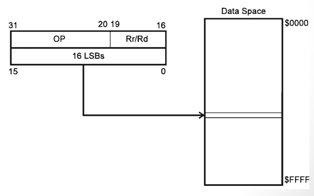
Instructions with this addressing utilizes 16 bit value k (0 - 65535) which is an address that corresponds to a space in memory, including the Extended I/O addresses scuh as UBRR0H and UCSR0A.
One instruction with Data Direct addressing is LDS Rd, k which loads the value in address k to register Rd.
Data Indirect (Rd/Rr, X/Y/Z +/- q)
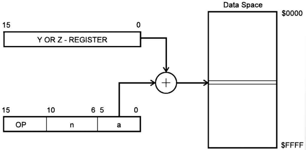
Registers X, Y, and Z corresponds to certain 16 bit register pairs in the memory.
| Register | Higher Byte | Lower Byte |
|---|---|---|
| X | R27 | R26 |
| Y | R29 | R28 |
| Z | R31 | R30 |
Instructions with Data Indirect addressing operates on data stored in the address stored in the X/Y/Z registers. For example, if X contains the value 0x01FF, then LD Rd, X would load the data value stored in address 0x01FF into Rd.
A feature of Data Indirect addressing is pre/post increment/decrement operators. By adding '+' or '-' next to the X/Y/Z register (eg: X+), the address stored would be automatically incremented or decremented respectively. This operation can be pre-ordered or post-ordered meaning the address value change would happen before or after the instruction itself.
As an example, assume Y = 0x02. Instruction LD Rd, Y+ would store the value DS(Y) into Rd THEN increments Y to be 0x03. As opposed to this, putting the increment operator before Y (LD Rd, +Y) would first increment the value of Y to be 0x03 THEN loads the data in the newly updated address into Rd.
This may come in handy when operating with arrays stored as blocks of consecutive memory.
Certain instructions also allows accessing memory with displacement q on pointer registers Y/Z (X gak diajak). These instructions, usually ending with D, such as STD Y+3, Rd would offset the address stored in Y by 3 which stores the value in Rd into address DS(Y+3).
To see which instructions uses which memory addressing methods, refer to the AVR Instruction Set Manual. Knowing which instructions utilizes which memory addressing method would help you choose the best instruction to use in different situations when handling arithmetic and logic operations.
No comments to display
No comments to display