3. Input/Output (I/O) Programming
On the Arduino Uno (ATmega328P), digital I/O is controlled through Port B, Port C, and Port D. Each port is 8-bit, allowing control of up to 8 pins simultaneously.
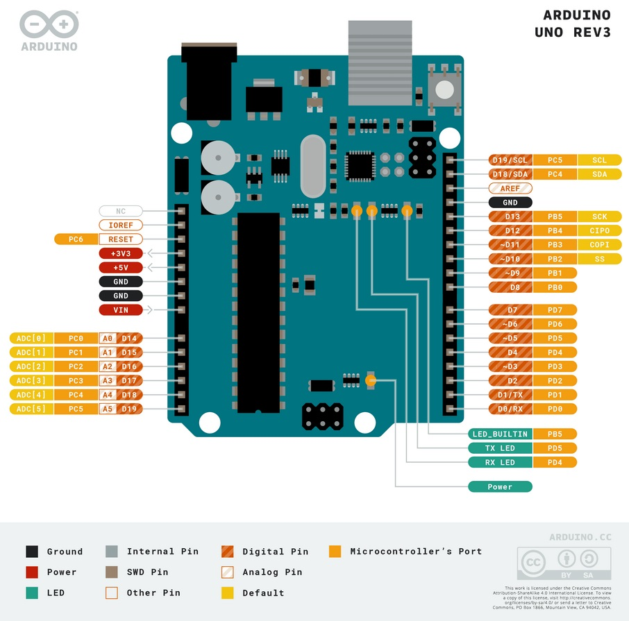
A. Port to Arduino Pin Mapping
| Port |
Bits |
Arduino Pin |
Notes |
| Port B |
PB0 - PB5 |
Digital Pin 8 - 13 |
PB6-PB7 are used for crystal oscillator |
| Port C |
PC0 - PC5 |
Analog Pin A0 - A5 |
PC6 is the RESET pin |
| Port D |
PD0 - PD7 |
Digital Pin 0 - 7 |
PD0 (RX) and PD1 (TX) for serial communication |
B. Main I/O Registers
Three main registers control the behavior of each port:
| Register |
Full Name |
Access |
Function |
| DDRx |
Data Direction Register |
Read/Write |
Configures pin direction. 0 = Input, 1 = Output |
| PORTx |
Data Register |
Read/Write |
If Output: Sets logic High (1) or Low (0). If Input: Activates internal Pull-up resistor (1) or Tri-state (0) |
| PINx |
Input Pins Address |
Read Only |
Reads the physical logic state of the pin (0 or 1) |
(Replace 'x' with Port name, e.g., DDRB, PORTB, PINB)
C. Register Bit Configuration Details
DDRx - Data Direction Register
| DDRx Bit Value |
Pin Direction |
Explanation |
| 0 |
Input |
Pin is configured as input (high impedance) |
| 1 |
Output |
Pin is configured as output (source/sink current) |
PORTx - Data Register (Depends on DDRx Configuration)
| DDRx |
PORTx |
Mode |
Pin Condition |
| 0 (Input) |
0 |
Tri-state (Hi-Z) |
Pin is floating, no pull-up |
| 0 (Input) |
1 |
Input Pull-up |
Internal pull-up resistor active, pin defaults to HIGH |
| 1 (Output) |
0 |
Output Low |
Pin outputs 0V (GND) |
| 1 (Output) |
1 |
Output High |
Pin outputs 5V (VCC) |
| PINx Bit Value |
Pin Status |
Explanation |
| 0 |
LOW |
Pin voltage is below threshold (near 0V) |
| 1 |
HIGH |
Pin voltage is above threshold (near 5V) |


No comments to display
No comments to display