
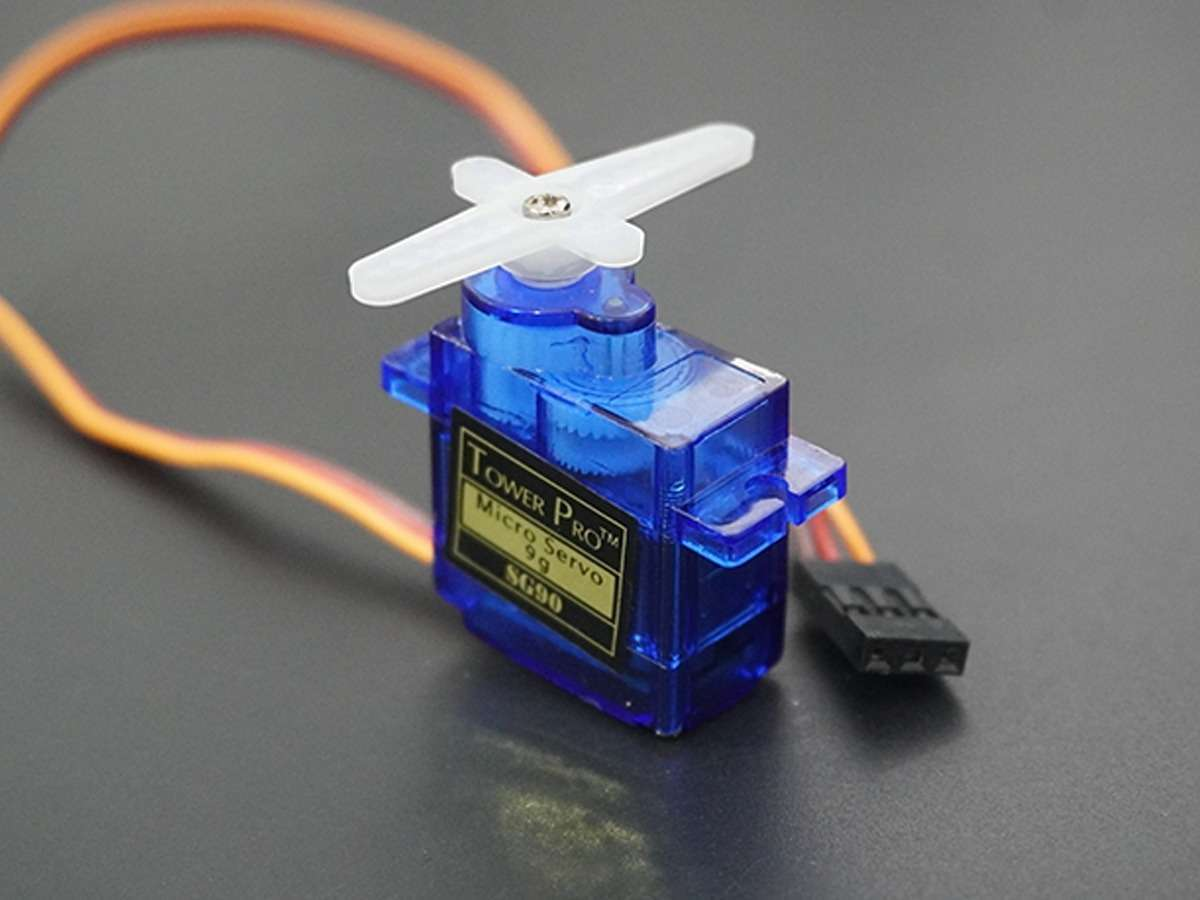
2. Servos
Servos are motors that adjusts to certain angles following certain PWM pulses.
Servo Signal Operation
Servo operates with 20 ms PWM periods.
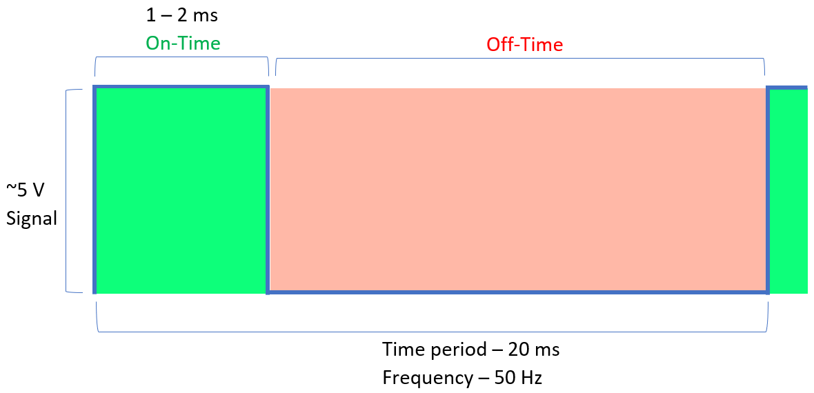
| Parameter | Typical Value |
|---|---|
| PWM Period | ≈ 20 ms |
| Pulse Width | ≈ 1 – 2 ms |
Servo operates with 20 ms PWM periods. This can hardly be achieved with Timer0 since Timer0 is an 8-bit timer.
This means its maximum counter value is:
2^8 - 1 = 255
20 ms period is hardly achievable with this which requires a 16-bit timer is preferred.
This allows precise generation of long PWM periods.
Using a prescaler of 8:
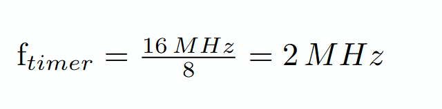
Timer tick duration:

Required servo period: 20 ms
Number of timer counts required:

Servo Initialization Code Example
SBI DDRB, 1
Configure OC1A pin as output. Timer1 will control this pin automatically.
LDI R22, (1<<COM1A1) | (1<<WGM11)
STS TCCR1A, R22
TCCR1A configuration:
| Bit | Purpose |
|---|---|
| COM1A1 = 1 | Enable PWM output on OC1A |
| WGM11 = 1 | Part of Fast PWM mode selection |
This connects Timer1 to the output pin.
LDI R22, hi8(40000)
STS ICR1H, R22
LDI R22, lo8(40000)
STS ICR1L, R22
Set ICR1 = 40000.
This is to make the Timer 1 count to 40 000 following the previous calculations.
LDI R22, (1<<WGM13) | (1<<WGM12) | (1<<CS11)
STS TCCR1B, R22
TCCR1B configuration:
| Bit | Purpose |
|---|---|
| WGM13 + WGM12 | Complete Fast PWM Mode 14 |
| CS11 = 1 | Prescaler = 8 |
This starts Timer1 in Fast PWM mode.
Servo Initialization
; Sets Timer1 PWM in PB1 to use period of 20ms by using Fast PWM.
; Timer1 counts until ICR1
SERVO_init:
  SBI DDRB, 1

  LDI R22, (1<<COM1A1) | (1<<WGM11)
  STS TCCR1A, R22

  LDI R22, hi8(40000)
  STS ICR1H, R22
  LDI R22, lo8(40000)
  STS ICR1L, R22

  LDI R22, (1<<WGM13) | (1<<WGM12) | (1<<CS11)
  STS TCCR1B, R22

  RET
Servo Usage
  .EQU LEFT, 2400  ; Generates a 2400/40000 % duty cycle.

  LDI R16, hi8(LEFT)
  STS OCR1AH, R16
  LDI R16, lo8(LEFT)
  STS OCR1AL, R16
This code makes the PWM generate compare match at count 2400 this allows it to produce a 2400/40000 * 20 ms = ~1.2 ms pulse which is around 0 degrees.
No comments to display
No comments to display